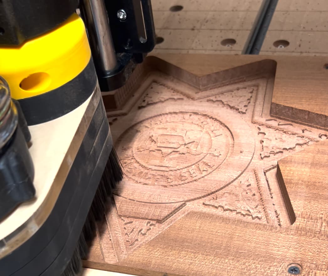
Hello, I’ve had my Elite Journeyman up for about 3 weeks, and I decided to do a 3D carve of my son-in-law’s badge. This is what it looked like in VCarve with very high modeling resolution.
Not even close to the same resolution. From reading other forums I get the impression that the carved model should turn out like the rendered model, unless there is something wrong with the CNC. Is this true, and if so what are some things I can look for.
One additional point I’d like to make is that although your workpiece appears substantial in size, the 3D model may still lack sufficient vertical height (detail) in areas such as the letters or the inside of the leaves, making it challenging to carve into wood even with a 1/32" bit.
For reference, I’ve been designing a highly detailed badge from scratch, manually drawing all vectors based on a photograph. Despite being limited to a height of just 4 inches, I’ve successfully reproduced this badge on a 1/8" thick brass plate. Achieving such fine detail requires me to use an Amana 45611 bit with a .005" tip (0.13mm), which less than 1/128" in diameter. To ensure precision, I’ve meticulously crafted the 3D model in Aspire, utilizing multiple layers and adjusting parameters like the “base height” of letters to accommodate this small bit and the tiny letters. Considering brass’s superior detail retention compared to wood, I hope this example provides some perspective for what you are trying do do.
Given the potential graininess of the wood, as mentioned by AndyP, I think your 3D model may need increased detail, and perhaps using an even smaller bit along with a different wood type.
A suggested test involves:
Import the 3D model into Vectric at a larger scale, such as double or triple its original size.
Drawing a small vector (e.g., circle or square) around a portion of the 3D model, roughly 3-6 inches wide.
Generate 3D toolpaths confined to this limited vector area to assess the results.
If the outcome is satisfactory, gradually reduce the size of the 3D model until detail loss becomes evident, thus determining the limitations of your model, bit selection, and wood type for the desired end result size.
Concur with all of this and it does look good! There is a setting in the 3D Roughing toolpath called “Machining Allowance” which is how much material to leave after running the toolpath. If this amount of remaining material is equal to or less than the abilities for whatever bit you plan on using next, you may be able to reduce the number of bits and the time.
Also suggest paying attention to your stepover for each bit. The roughing paths can be large (e.g. 50%) and will significantly reduce carving times. For the final finishing pass, I suggest being no more than 10%. Sometimes I will take it as low as 8% stepover depending on the bit and material.