Two stepper motors on one driver

I wanted to know if anyone has had success - perhaps on other CNC machines - connecting two stepper motors to one driver output (such as the two on the y rails). I am interested in the possibility of freeing up a controller driver for a future 4th ‘C’ axis use. Are there any negative impacts of this?

I reached out to BuildBotics, and part of the response is as follows:

“… you may be able to wire the two motors onto a single port thereby freeing up the fourth port for your tangential knife. Oftentimes (but not always) wiring two motors to the same port results in resonance problems between the two motors resulting in motor stalls. Unfortunately, you won’t know whether this is a problem until you try it.”

I appreciate any insights those with experience may have.

Tom

Personally, I would not do it directly. I would use a breakout board, but in theory it would work since there are no encoders being used for feedback. The only thing I’d maybe worry about is the fact that homing is apparently done via stalling the motors. (I haven’t got mine up and running yet to see exactly how the homing routine is implemented) Come to think of it, a breakout board might be a way of incorporating encoder feedback or servo drives without having to modify the controller hardware/software itself. Just thinking out loud …

I was thinking the same thing. Have you tried it yet? I was also wondering how to wire the Y axis motors in series. You can see my other poste here. I would have liked to wire the Y motors in series and then add an A axis if possible.

I did two stepper motors in parallel for the Y axis on a laser engraver. It worked fine for me. I made sure the wire lengths was identical for both motors.

I was reading that in parallel it makes the wires heat up more and draw more amperage. I don’t know which is the correct way to wire them, series or parallel. I’m looking for a wiring diagram so that I don’t make the motors go opposite directions and jam up my machine. haha

Would you please share your wiring diagram? Thank you in advance!

I would be worried about drawing too much current and damaging the controller. For a laser there’s not much draw on the steppers but carving could. Ideally what you would want is to have drivers for the steppers not in the controller. It would be nice to see a schematic of the 1F controller. It should be possible to tap into the signals going into on board drivers inside the controller and add external ones.

Controller version 4 and 5 are on github:

Thank you for the responses! I’m very new to this and I’m a designer, not an engineer or tech so I think I’ll wait until someone has done it successfuly before attempting it myself. I wanted to free up a driver to use for a rotary axis but I’ll just swap my Y cables with an A cable when I need to use the rotary.

1 Like

Hey Bruce,

the following citation applies to Buildbotics Controller V1.0 and since Onefinity CNC Controller is a hardware fork of Buildbotics Controller, especially driving the four stepper drivers applies too. Note that you always should have a look at the schematics (of both Onefinity CNC Controller and Buildbotics Controller) in order to know what you’re doing, especially regarding maximum power for all stepper motors.

At the end of the citation you find what Buildbotics say about using two stepper motors on one single port (which is what you would intend to do with your two Y stepper motors in order to free the fourth stepper motor port for your new rotary axis A).

3.6. Motors

The Buildbotics Controller has four motor outputs, labeled M0, M1, M2, and M3. Each motor output can drive a separate axis, or two motor outputs can be assigned to the same axis. One or more motors can be connected to a single motor output. If more than one motor is connected to a single motor output, they can be wired in series or parallel.

The motor driver outputs can supply up to 6 amps peak current to each coil. Each motor has two coils. If multiple motors are connected to a single motor output and they are wired in parallel, then those motors will share the current equally. The current through each motor coil is an approximated sine wave and there is a 90° phase shift between the two coil drivers on each motor output. Since the currents are out of phase, the peak total instantaneous current to a single motor output can be as high as 8.48 amps.

The total average motor current is limited to 10 amps. But, the sum of the peak motor currents can far exceed 10 amps.

Exceeding 10 amps of average current will cause the controller to shut down with a “Motor overload” fault. The average current drawn depends heavily on the load placed on the motors.

Users should refer to the data sheet for the motors being used and configure the motors for the current rating shown in the data sheet. See, the configuration section of this manual for more information on this subject.

The voltage output to each motor driver is a pulse width modulated (PWM) voltage with an amplitude equal to the input DC voltage being supplied to the Buildbotics Controller from the power supply.

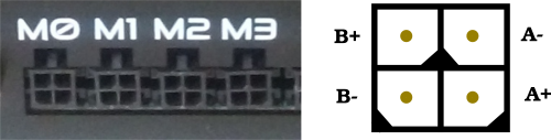
The motor output connectors are shown below. All four motor output connectors are wired the same. The motor output connectors mate with Amphenol 10127716-04LF connectors equipped with Amphenol 10127718-001LF female crimp pins.

Buildbotics Controller motor output connectors

When connecting motors:

  • Connect the B+ pin (upper left) to the positive side of the B coil on the motor.
  • Connect the B- pin (lower left) to the negative side of the B coil on the motor.
  • Connect the A+ pin (lower right) to the positive side of the A coil on the motor.
  • Connect the A- pin (upper right) to the negative side of the A coil on the motor.

These connections will cause your motor shafts to turn either clockwise or counterclockwise. If the motors are turning in the wrong direction, simply reverse either the A+/A- pair or the B+/B- pair. Do not reverse both pairs.

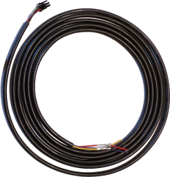
It takes some practice to properly attach the Amphenol 10127716-04LF connectors equipped with Amphenol 10127718-001LF female crimp pins to a cable. In order to avoid this difficulty, the Buildbotics Controller includes four, 10-foot motor cables with connectors that are compatible with the motor output connectors. Buildbotics motor cables are wired as shown in the following table.

CONDUCTOR PREMADE CABLE WIRE COLOR
A+ Red
A- Black
B+ Yellow
B- Purple

Buildbotics pre-made motor cable

Some CNC machines use two motors driven on a single axis. If an unused motor output is available on the Buildbotics Controller, simply assign the second motor output to the same axis and connect the second axis motor to the second output.

A single output port can drive two motors with certain limitations. It is recommended that the motors be wired in parallel when driving two motors from a single motor output. The limitations are:

  • Since the two motors are wired in parallel, the current supplied by the motor output will be doubled. For instance, if each motor has a current rating of 2.8 amps, then the current on the motor output must be set to 5.6 amps. The maximum output current from a motor port on the Buldbotics Controller is 6 amps, so you cannot connect two motors that require more than 3 amps each to a single port.
  • When motors are wired in parallel on a single output port, they tend to resonate with one another. When the resonance occurs, the motors will stall. As a result, the motors must run at a speed below this resonance to avoid stalls. Unfortunately, it is not possible to predict the speed at which this resonance will occur without wiring them up and connecting them to the machine.

In many cases, the two motors will face one-another and must turn in opposite directions.

If the motors must turn in opposite directions, then one of the motors will have either the A+/A- pair reversed or the B+/B- pair reversed (but not both). The following image shows the B+/B- pair reversed on the motor on the right which causes the motors to turn in opposite directions.

Parallel motors wired to turn in opposite directions

Refer to the Motors tab on the Settings Page for information on configuring motors.

– Source: Buildbotics Manual V1.0 → #Motors

Further Reading

How to Wire Stepper Motors
DRV8711 Datasheet – Texas Instruments

4 Likes

This is wonderful, thanks so much Aiph5u!!
I just finished setting up the A axis motor. With a bit of tweaking it seems to be working. So I’ll certainly try this next. I just need to order a couple of extra cables from Onefinity first.

Thank you very much again!
Cheers

2 Likes

@Bruce_T did you ever give this a try? I’m headed down the rotary path myself with the standard (buildbotics) controller and am trying to determine if this method will work instead of swapping out the X or Y axis completely.

I don’t know how stall homing would work if two motors are tied together. I would think that you would need to add limit switches possibly wired in serial.

1 Like

@Dr-Al sounds like that method might be above my pay grade. :grimacing::joy:

Can you explain the stall-homing concept? The only concern I previously saw was around possibly stalling both motors if resonance occurs between the two motors on the same driver.

With the buildbotics controller it homes by forcing each stepper motor to it’s limit. For the Z axis it’s all the way up, the X is all the way to the left, and the Y is all the way to the front. Since the Y axis has two steppers the controller monitors each one separately. If the two Y axis steppers aren’t exactly in line with each other the controller will bring them back in line.

If you tie the two motors together I’m not sure what would happen if one reaches it’s limit but the other hasn’t. It may not be an issue. I assume the stall current setting would need to be raised so just one stepper wouldn’t trigger the controller into thinking both reached home.

1 Like

What has not been mentioned here is that once you remove power of X or Y axis motors there is nothing to hold the axis in position.

It is absolutely necessary to get pipe clamps to secure the non moving axis, the vibrations and lateral forces of the bit cutting the workpiece will move an unsecured axis.

I have been through all of this and have decided that all the problems of converting the buildbotics controller to run a rotary really is not worth my time. There are so many obstacles, from zeroing without the limit switches (imprecise stall homing), changing the configuration to rotary and back, switching those tiny little cable connectors behind the controller (worst if it is mounted under the table), and many more, and then finding out that VCarve really has rotary related software bugs. And when the buildbotics starts to glitch you have to start all over again. No fun at all.

I really would recommend anyone wanting to use a rotary to get the Masso controller.

I do not really think that is correct. See here:

https://forum.onefinitycnc.com/t/why-are-they-uneven/14346

Hey Daniel,

Stall homing (=bumping against the travel end) (➪ see also here)

See also

Retrofit limit sensors

Two steppers on one stepper driver