In making a Meyers style waste board I was faced with a problem. I didn’t want to drill the holes below the bottom ( usually I go -.03125 ) as I would usually do when I am using a waste board, because that would cut into the top of my table, so my strategy was to drill the center holes all the way to the bottom without breaking through, and then flip the board 180°, re-home the machine, re-probe, and finish cutting the holes from the bottom side.
The first thing I did was to flip the model in Fusion exactly the way I would be flipping it for real. I output new g-code from the new model position.
I was very careful to make sure the board was perfectly square and the xyz probe was done carefully, but the holes got drilled off center by a little bit, and now the board is useless. Does anyone have ANY idea why this might have happened?
My closest guess is that all of my measurements in Fusion were done in Imperial, and I know the machine is based on metric.
Is it possible that the small translation inaccuracy between Imperial and Metric could be the culprit?
This flip operation assumes the workpiece exactly matches the CAD model, and the CAD features are symmetrical and centered on the axis it was flipped on. Imperial or metric, doesn’t matter so long as you’re consistent. Using a base 10 numbering system is more common and less error-prone, but some stubborn guys will make silly arguments against that, but that’s a digression into its own thread.
If you XYZ probe the workpiece from the bottom corner, this introduces more failure points since the probe is only as good as the calibration and how accurately you measure the workpiece dimensions. 2-sided jobs work best if you use indexing pins on the center of an axis and use that center for X or Y origin. I’d bet the operator is this problem’s culprit, not the machine doing something other than what was asked of it.
An easier strategy vs flipping and trying to drill again is to elevate the wasteboard above your table with some 1/4" MDF, for example. Drill through by 1/8" and call it good.
A flipped job that doesn’t come out right (even if everything has been set up & programmed properly) has likely revealed an out-of-square condition of the machine.
@sigung I feel your pain. I had the same problem trying to make Red dogs wasteboard system. Nothing wound up lining up properly when I flipped the pieces over. Gave it up as a lost cause and set the machine to drill 7/8 through the MDF and then rudely drilled the rest of the way through with the drill press. Another project required drilling more than 100 1" holes in 1/4" Baltic birch ply. To ensure they were clean, I set it up to drill through both sides, flipping the sheet and aligning it up with pins mounted in the spoilboard. Couldn’t get this to work right either so wound up just doing the holes all the way through in two passes with a down cut spiral bit. Results were really good, just went over the back side with a random orbit sander to clean up the breakout and was frankly stunned by how clean it all came out. So…still trying to figure out two sided CNCing.
Probing twice does not ensure two-sided machining will work without a way to register the work piece. Typically, the dowel pin method is used. This is what I did for my wasteboard. Two 1/4" thru holes on side 1 along with two 1/4" holes in the table top are used for 1/4" dowel pins to register the stock when flipping to side 2. No need to re-zero X and Y for side 2 if done right There are youtube videos showing this method for 2-sided CNC work.
I’m using a similar wastboard design. You mentioned you didn’t want to bore holes all the way into your table surface. Can I ask how you are planning on attaching the Meyers waste board to the table?
My very first operation was to bore mounting bolt holes into my table, and those holes were the exact diameter of my bolts so it was a very tight fit. This will essentially become my alignment pins for the remaining waste board operations.
Then I attached my fresh waste board to the table top and ran the second & third operations, which was to bore washer recesses and bore the same mounting holes in my fresh waste board.
All subsequent operations should use the same X/Y/Z points so simply flip the piece over, attach it with the bolts (I installed t-nuts beneath the table surface to receive my mounting bolts), then run the next operation.
When I flipped my wasteboard over to mount it to my table, this is when i realized the OF assembly video failed me. My machine was a parallelogram so I needed to re-square my machine and start completely over with my wasteboard. Sadly, this also meant I had to plug the holes in my table top so I could bore fresh mounting holes.
In my case, the workpiece exactly matches the CAD model, and the CAD features are symmetrical and centered on the axis it was flipped on.
All things being equal, the probing was done at the same place with the same probe with the same care. This was one of my original ideas as to the culprit, but even if there is an error is introduced in the way of a mis-measured or compensated probe, if the exact same error is introduced on both sides, it seems it should work anyway.
I agree the elevation idea is good, I just didn’t have the material on hand to accomplish it.
Thank you for your intelligent and thoughtful input, it’s most appreciated.
Referencing the table end, is of no help to you. Your references should be to against your machines position.
Have you checked your machine for square?
And your method to attach the spoilboard - I believe the question was aimed at your permanent fastening method, not just for initial milling. Which all the points Eric has pointed out, would definitely help.
since you have ruled out the possibility of any of the proposed causes being true, there can only be one conclusion: The problem you described did not occur!
You write your machine is perfectly square. May I ask, how do you measure the squareness of your machine?
Actually, referencing the end of the table IS of help to me, since I’m starting off with a perfectly square piece of MDF, that puts the MDF perfectly square with the end of the table, and to answer your second question, the machine was squared up in the beginning to the table with that 26" Woodpecker’s 2616 square you see in the storage tray at the bottom of the table - accurate to .001", so yes, the table is square, the machine is square, and the machine is square to the to the table as well. All are reference surfaces.
And as to the question of the permanent fastening method, this IS the permanent fastening method. The T-Tracks are permanently mounted, and the clamps keep the waste board in place just fine, which makes for an easy replacement when it’s time to, and I don’t have to keep hogging out previous mounting holes every time I replace the waste board using this method.
The machine was squared up in the beginning to the table with that 26" Woodpecker’s 2616 square you see in the storage tray at the bottom of the table - accurate to .001", so yes, the table is square, the machine is square, and the machine is square to the to the table as well. All are reference surfaces.
Now to answer the question I initially posed, I’ve found the culprit. Please see my solution post below.
Hi fellow CNCers. The culprit turned out to be what is generally the most common problem. Operator Error. IE ME
Everything was set up correctly but I flipped the waste board wrong. I didn’t flip it the way I flipped it in the CAD ( Fusion ) program.
The second mistake I made was that when I set up the boring operation, I only had it go to .25" below the top instead of all the way down.
I think the reason that that was a problem is because of the nature of the boring operation.
In this case, my bit was .25" but the hole needed to be 0.28125" to accommodate the OD of the T-Nut, so the boring operation spirals around the ID of the hole. With it not going all the way down to the other side, ( mind you, I’m not sure about this ), but I think it might have left a partial wall near the bottom that was causing a misalignment problem with the screws ( they were tilted on the first go around when I tried to put them in. )
So all is working well now, but if you all have any further thoughts, they can only serve to help the community.
Good of you to contribute your solution and admit to mistakes- we ALL make ‘em. The trick is to learn from them and learning from others’ mistakes… well, that’s almost cheating but it’s a great way to help our community of knowledge.
That’s an interesting way to secure the waste board. I’d be curious to hear how that works long-term. My fear would be chips & sawdust getting packed down into your t-nut holes, eventually finding its way under the waste board & causing a crown in the middle of the waste board. Or up-cut bits potentially raising your waste board upward enough to cause unintentional too-deep carves…? But on the plus side, your waste board is super easy to remove to clean out the debris!
Yeah, I’ve done a similar arrangement for almost a year now, and it works very well. The OOPS clamps are a new addition as a result of me running a bit into my gigantic Rockler clamps…
The reason I asked is because your end of your table has multiple saw blade marks. There’s no way it’s square. I can see those from here. There’s no advantage to asking questions and getting defensive when someone offers suggestions or questions your methods (right or wrong).
And that hold down method, is going to be very problematic, again like Eric mentioned. With no middle fasteners, you’re going to get movement on every carve, dust creep, if there’s any bit lift, temperature change, threaded fasteners and Teflon clamps are sure to loosen over time as well, you name it. I would reconsider fastening more than every 1 sq ft, personally. Again just advice…
I think my reply was spot on and very even tempered. I’m answering everybody’s questions to the best of my ability and as accurately as I can. You, on the other hand, seem to be a very sensitive individual, perhaps reading things into my replies that are not really there.
As far as the saw marks go, you’re looking at the wrong reference. There is a 30" t-track screwed to the front of the table, and the saw marks are incidental and small and have no bearing on the overall squaring up that I’m doing.
As far as the hold down method goes, I think I already mentioned I’ve been using it for over a year with no problems, so there’s that…
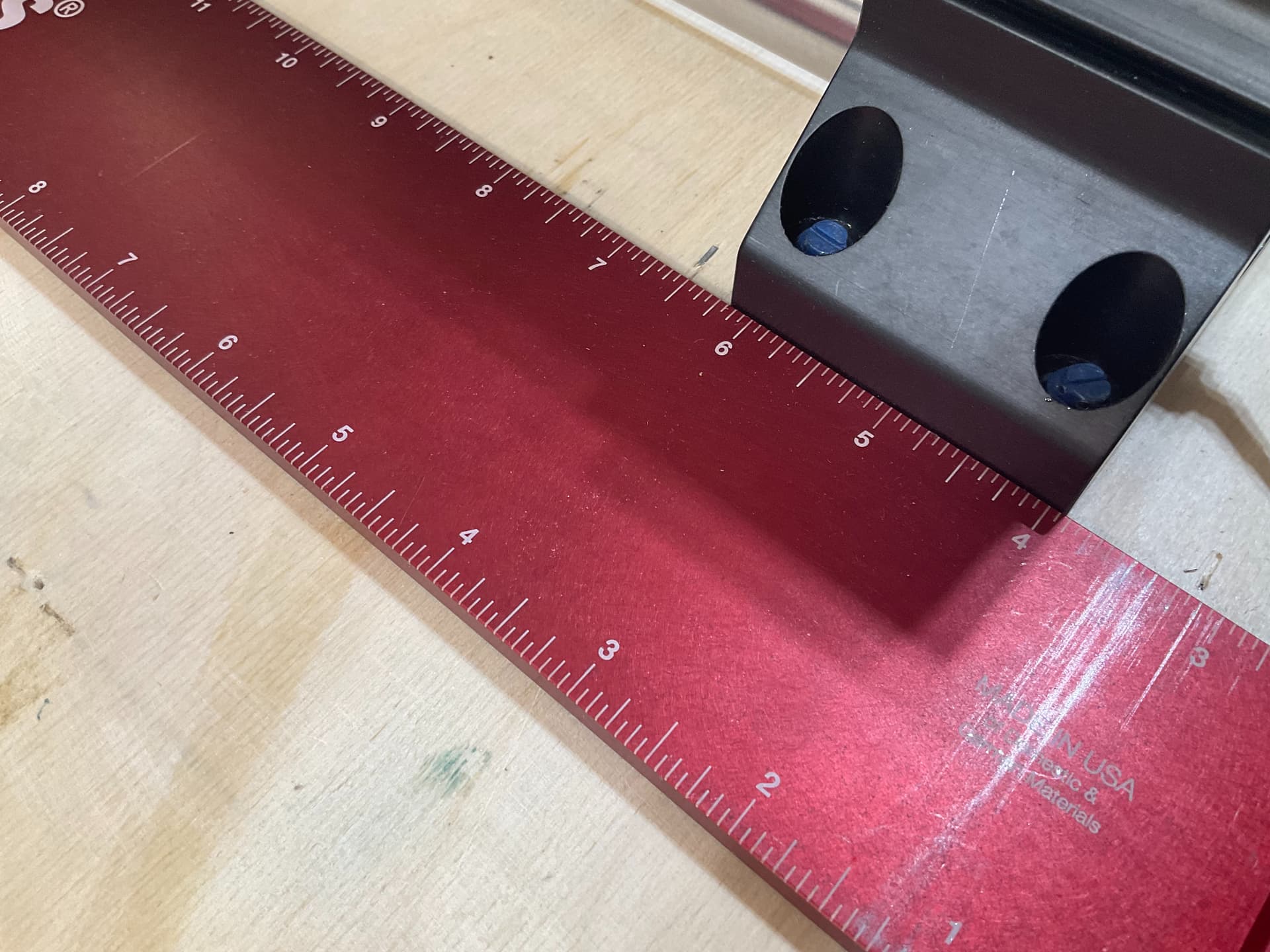
The X-Beam foot is exactly 7/8" further in than the front foot of the Y rails. What you are looking at is a very precise square referenced on the front from the aforementioned T-Track, then at the rear, you see two Veritas setup blocks put together to make a 7/8" spacer. Hopefully you can see that the machine is square and it is also square to the table.