Help! Fusion360 CAM is killing my MDF!

Hi! Full discolsure: I am new to Fusion 360 CAM.

I am trying to make a drill template for my spoilboard. I plan to use it to accurately place t-nuts. So I decided to use the 1F to make the drill template.

The machine is square within a .5 pencil mark. I checked accuracy with a 1 meter precision ruler and even with magnifying glasses it appears to be spot on in both X and Y directions. I used Charlie’s Triquetra software to measure my touch plate. (Ran it 4 times and averaged the results.)

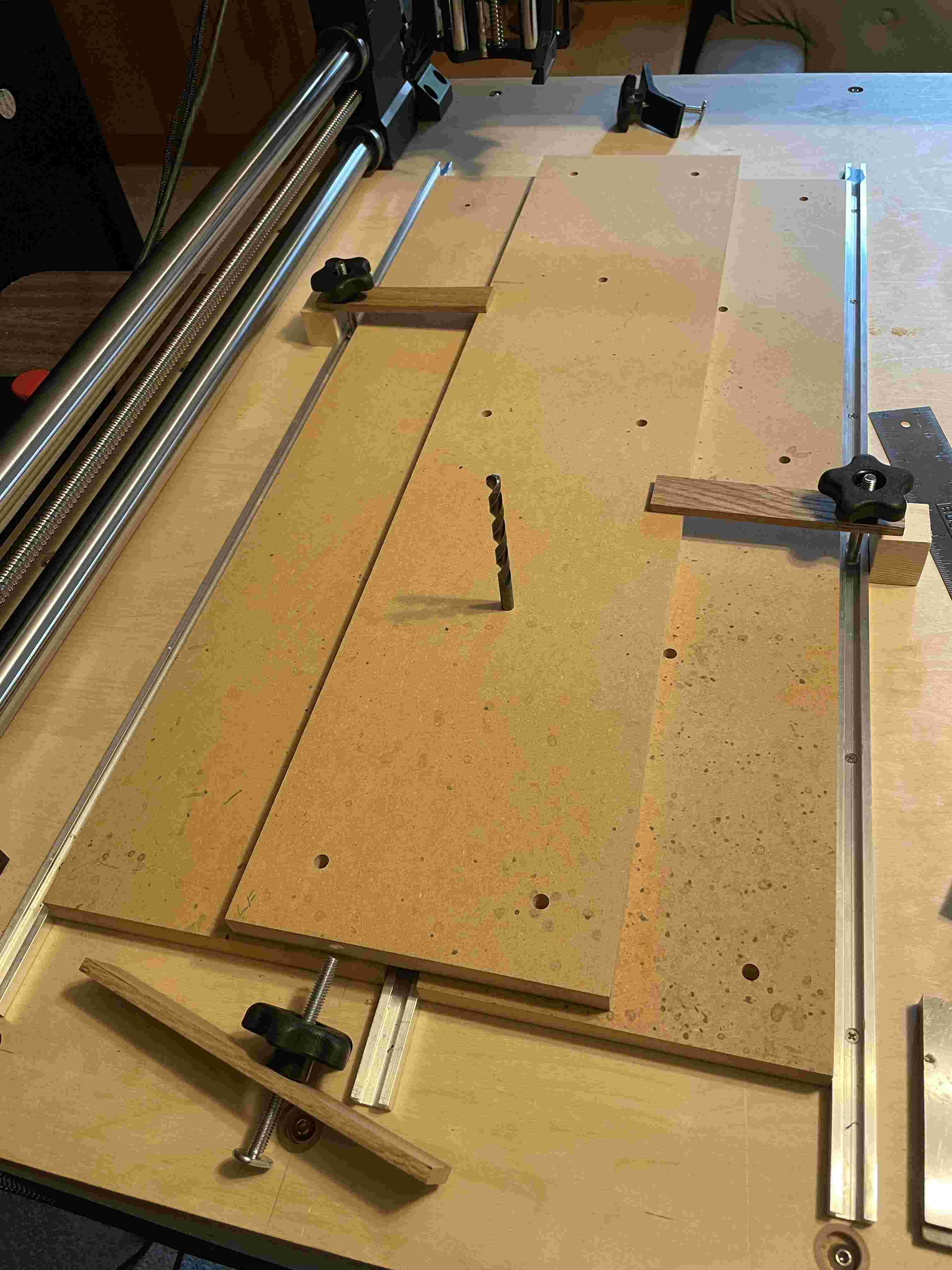
My first attempt resulted in holes that were off… Not much… but were off. I assumed I didn’t have it lined up correctly so I went to much more trouble on my second try.

My spoil boards are 7.5" wide and have been cut very accurately. To make sure my second try to be used as the drill template was as parallel with the Y-Axis as possible, I used another spoilboard butted against the Y Rail as a guide to clamp my work piece in place.

Careful measurements afterwards showed that the board was as parallel as possible. The picture was taken after most of the clamps had been removed.

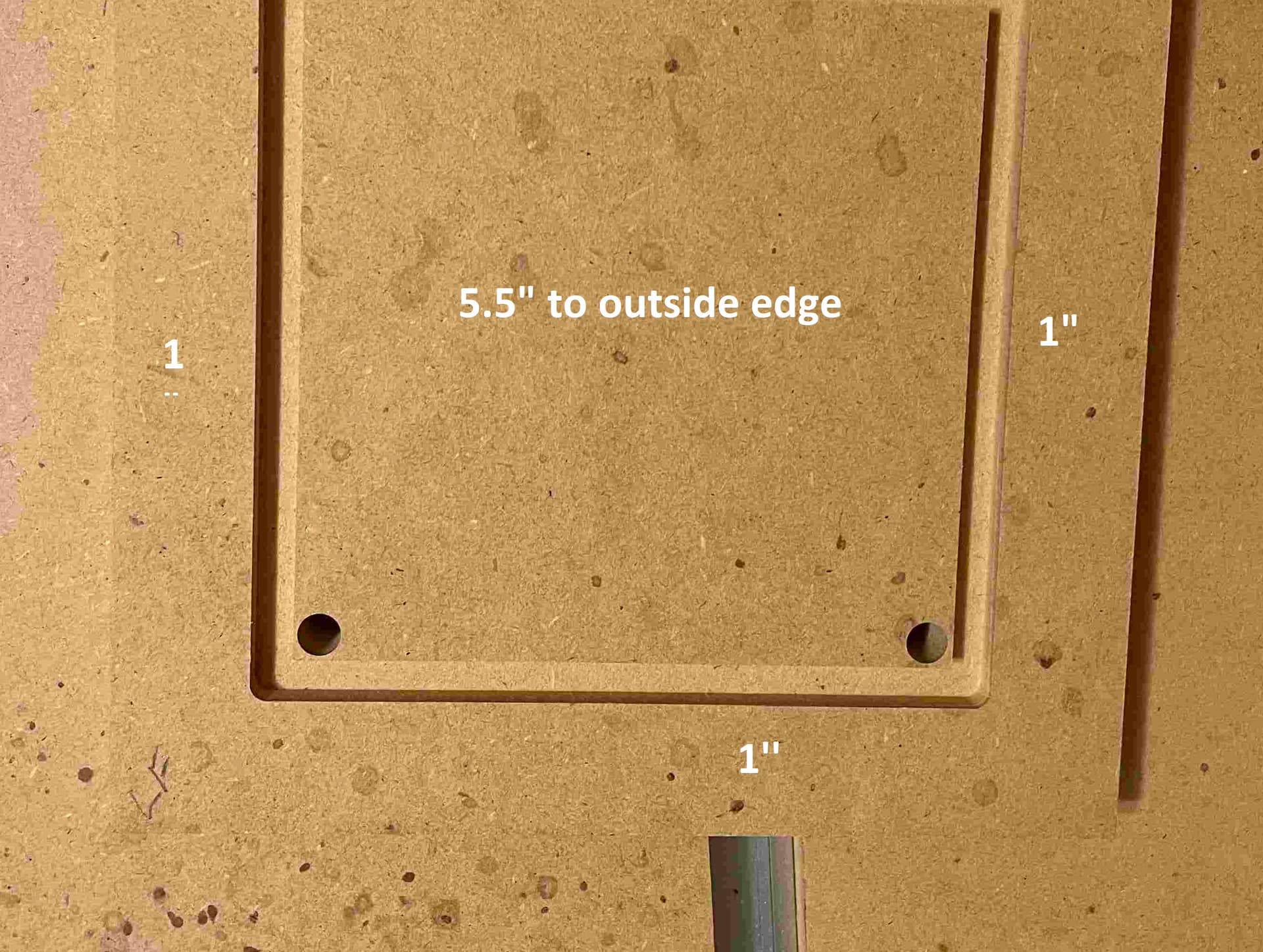
The holes are 5/16 and are quite accurate. Pushing a 5/16 drill bit into the hole actually causes a little pneumatic push back and a pop when removed.

The holes are still off. Not a lot… but too much to be used as a template. They are almost the exact same as on the first attempt.

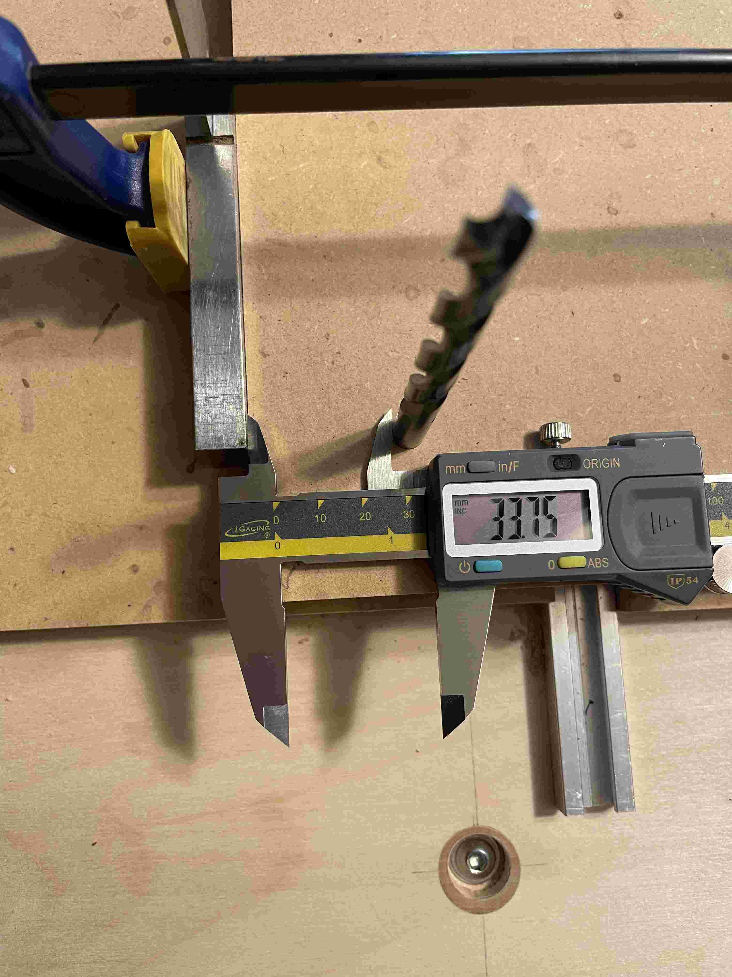
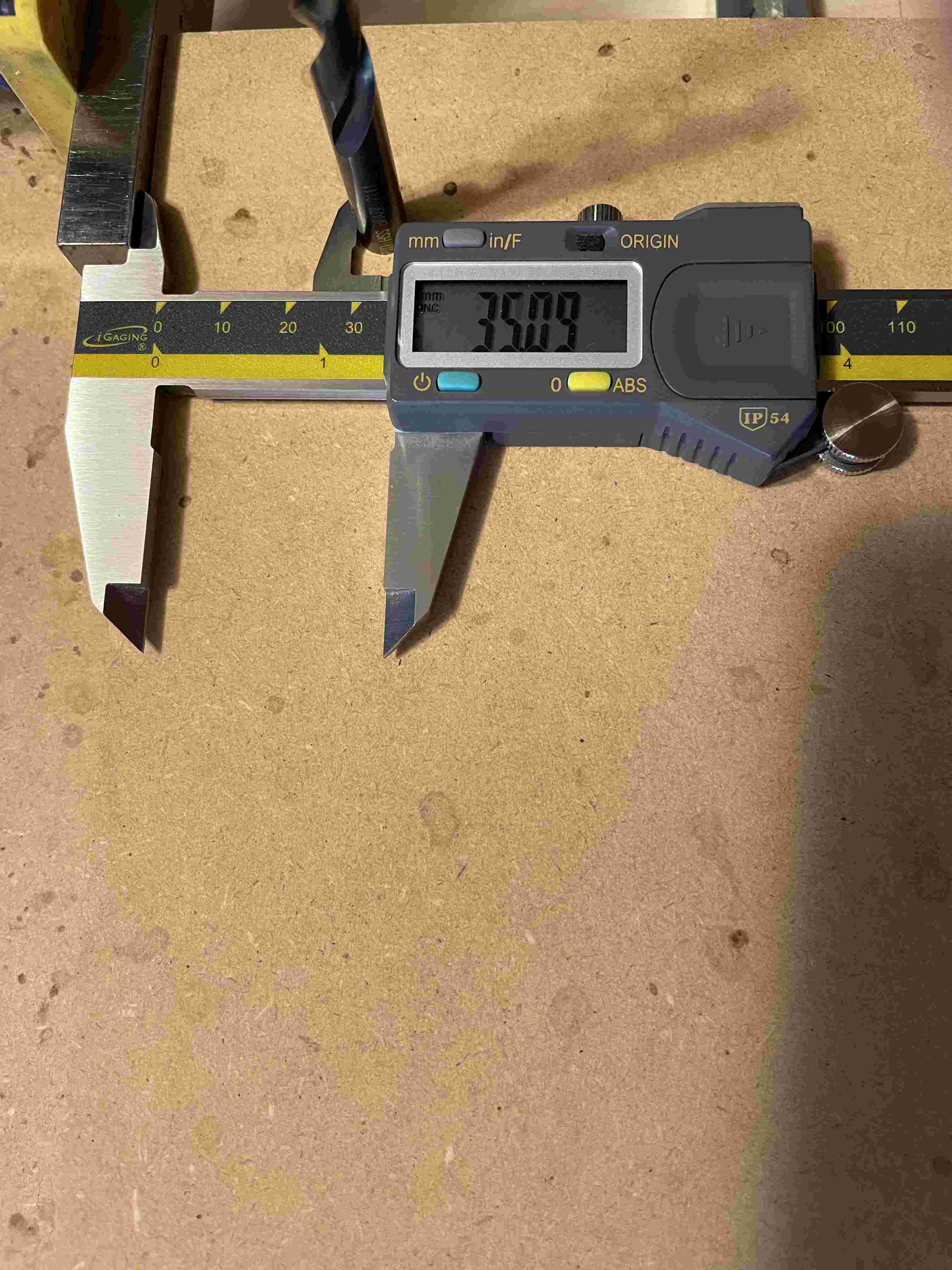
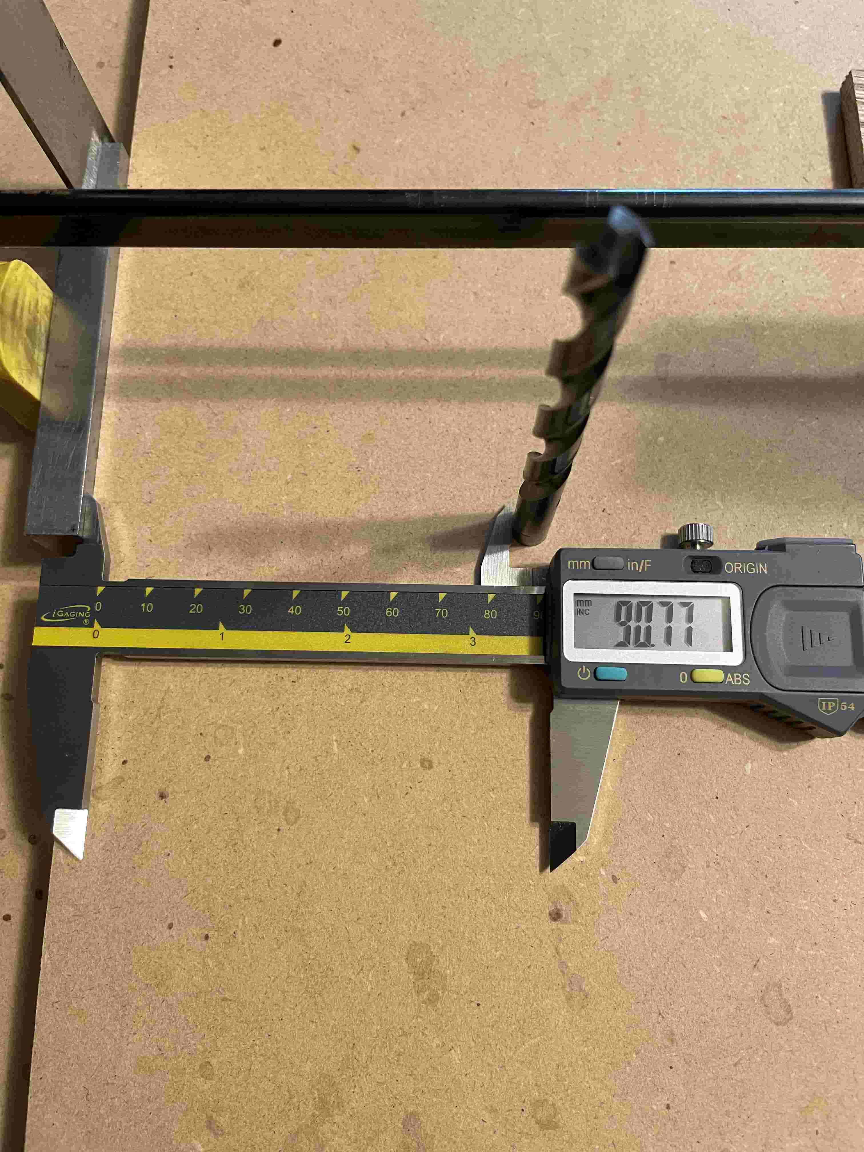
According to Fusion, the corner holes should be 34.125mm to the edge. The hole in the middle position should be centered. (91.275mm from the edge.)

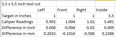
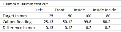
The pictures below show my measurments.

Left Side Edge

Right Side Edge

Left Side of Center

Right Side of Center

My first thought was that there was something wrong with the machine… but that doesn’t seem right because I am using a 1/4" bit to make a 5/16" hole very accurately.

One more thing: When I originally designed the Spoilboard template it was in inches. I converted it to mm in Fusion before going through the CAM steps. I found the link to the post processor on this forum.

The G-Code seems to run fine in Camotics but I couldn’t see a way of getting any dimensions as to where it would be cutting other than playing the file and trying to stop it. As best as I can tell it seems fine there.

I am sure I am just missing something. I have attached my G-Code and my Fusion file if this helps.

Thanks so much!

SB Drill Template LFO.nc (162.1 KB)

Spoilboard Drill Template v4.f3d (199.9 KB)

Hi Ziggy - based on your Fusion file, the center of the bottom left hole is 38.10mm from the side, or 34.125mm from the edge to edge as you indicate, leaving 0.375mm difference. That’s not huge, but certainly not within the specs I would expect.

Have you calibrated your X and Y axis to ensure they are traveling the proper amount? For a 5/8" hole the error would not amount to a lot, but the further you travel, the more the error. Though I will admit 34mm is not a lot of travel - I mean my machine was off by ~1.58mm over 812mm, which would be 0.066mm for 34mm–completely imperceptible by the eye.

Second - are you 100% sure your stock is 190.5mm wide? That is what your setup says.

Recommend making a few fixed size cuts using a v-bit if you have one - something like 100mmx100mm to see if you are getting the correct size regardless of position.

Let me know and we can dig further.

-Tom

1 Like

Thanks Tom!

I followed your guide for checking accuracy. I actually bought a 40" / 1 meter precision ruler for the purpose. Using a sharp point it appears to be dead on.

The stock is 7.5" wide so 190.5mm should be correct.

I don’t have a v-bit but I will try some test cuts as soon as I can get back.

What throws me is that the size of the holes themselves seems to be very accurate.

Ok… I created a few test cuts. Here is what I found.

The first cut was done in imperial. I basically cut a 5.5" square, 5/16" wide 1/4" deep trough. The pattern should have been one inch from three edges since the MDF is 7.5" wide.

The measurment on the right may be a little off because I have been using a ruler to cut my boards rather than a caliper. Maybe the board is slightly wide.


(The bottom edge is hard to see.)

Here are my measurments:
inch test

I also did the same type of thing in metric. This time it should have been a 100mm square, 10mm wide, 5mm deep trough.

Here are my measurments:
mm test

There two crazy things about the metric test. First is that instead of the bit ramping into the cut like the imperial test, it immediatly plunged the full depth. (Probably a CAM difference??) The second thing is more troubling. It plunged 12.5mm rather than 5mm. I assumed I screwed up the drawing but I checked it and it does indeed show 5mm.

More information:
It occurs to me that the differences I am sweating are on par with the differences I encountered when running the Triquetra G-Code to measure the touch plate. I ran it 4 times.

Triquetra measurments:
Triquetra

I am sure that Charlie’s code is good. It now has me wondering about the limitations of the machine itself. I am sure there is a mathematical way of figuring accuracy of turns vs movement and such. And it seems I have read something about microstepping… of which I am almost completely ignorant.

So I am not sure where to go with this. Maybe as I learn CAM better I can be more accurate in much the same way I learned to use conventional tools. As it is, this machine is just barely good enough for my intended purposes.

That being said, I am still new to CAM and this machine so I am trying to be a sponge right now and learn as best as I can. (I have to… otherwise I have a very large and expensive paper weight!)

Thanks again for all your help!

Here are the Fusion files for the post above.

Test Board inch.f3d (113.4 KB)
Test Board mm v3.f3d (112.9 KB)

@Ziggy are the test cuts in the same board? If you are going to be using different boards and want to repeat something precisely then I would suggest creating some jig boards along the left and bottom of your spoil board that are perfectly square so when you put a new piece of material in the jig two sides will always be in the same position. If you just try and clamp a piece in the same spot you will have small variations in the position of work piece from piece to piece. Not that this is what is happening but just a suggestion. There is a peg jig system that works just the same. The idea is every board starts in the same spot so you do not need to repeat the x and y probe between projects.

1 Like

Also when probing x and y its a good practice to hold the block down carefully while the probe is touching the block. I have actually seen the bit move the block as its probing when my material surface was polished.

Thanks JDog.

I was referencing off of the Y - rail with another board to get these parallel.

I slowed my movement down to 50 on the probe and I hold it as well.

I am thinking about trying to just eyeball X and Y with a pointed bit and then re-run the test.

Maybe I am just expecting too much. Maybe I was overestimating the 1F capability. I was hoping for something in the hundreths of a mm rather than in the tenths.

Did you confirm as Cyberreefguru asked that the steps/mm are calibrated? Definitely do that. Then, you said you measured the x and y separation (I think) but did you measure the diagonals between the corners of your machine? There was a whole thread on that subject. Both of the above are critical setup calibration/alignments to do, and dont forget tramming, before worrying about the capabilities. Its kind of painstaking work but kind of fun/zen to do.

Thanks!

The distance across X (between the Y rails is within a few hundreth of a mm. (Measured with a aluminum bar and calipers.)

The square measured from corner to corner is as close as I can see by eye. It is definely within a pencil mark. It is visually dead-on.

I am using inserts to hold everything down for ease of future use. So at this point I am trying to create the drill template that I need to drill the holes to mount the spoilboard.

I tried something the other night. I used a 1/4 drill rod with a sharpened point to find the edge of each side of my work piece. (I used magnifying glasses to judge as best as I could.) I then did the math to find the center. I now have a completely re-drawn spoilboard drill template and new CAM setup based off of X and Y being in center.

Later today I hope to set the X and Y origin manually and try this again.

I am starting to wonder if the touch plate is only to get you in the ballpark. I say this because of the readings I received when using the Triqueta G-Code. (I posted these above.)

Thanks to everyone for their help! I have been reading the other threads on accuracy and I watched the Onefinity YT video on accuracy. It seems the machine is capable of doing what I need. Since my warranty runs out soon I need to get some sort of resolution fairly quick. That being said, I feel certain the issue is me and my “newbieness” to CNC machining.