I am having some issues getting the journeyman X50 to cut square, I have scoured this forum and tried many of the suggestions but I just cant seem to come right.
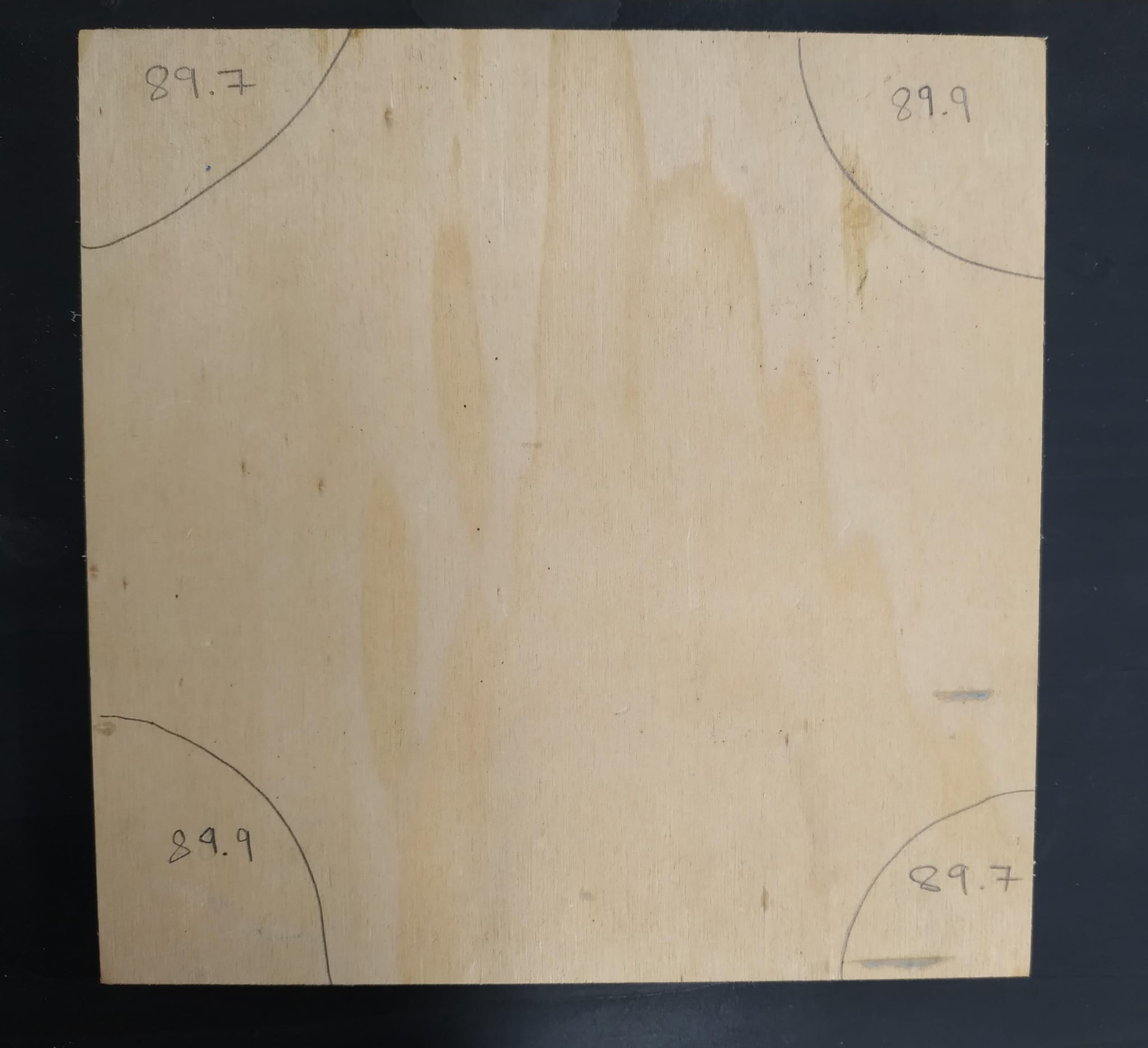
I noticed the issue when trying to cut wooden squares that need to be exact. The angles are close but not quite 90 degrees
Measuring diagonals with a laser shows the are the same to within a 10th of a mm. I did the 4 3 5 Triangle test and it showed that its square. I have redone and rechecked gcode from carveco. I have re setup the entire CNC, table top now has many holes… I attempted to adjust one side very slightly using the straight edge and carpenters square technique, which improved the 89.7 corners by about 0.05 but made the 89.9 corners about 0.05 worse. Any advise would be much appreciated . Thanks!
If your 2 rails are not true to each other it would cause the issue you are seeing are you sure your machine is not in a slight trapezoid? There are several threads on the forum addressing this issue, and how to ensure you are 100% square and true.
These methods are not as accurate as a bar gauge. See tolerance in the laser manual. Using a square is not accurate enough, and a square of this size and at same time of sufficient (and certified) precision would cost many hundreds of dollars/euros. The best method is the compare diagonals method, no measuring is needed, just a bar gauge to compare them. It is important to measure between the point where the chrome-plated, hardened steel hollow shafts go into the black anodized axis feet, and not on the base of the machine’s feet, because the steel shaft’s position can be adjusted inside the black anodized axis ends, on each end. Also it is important to consider that the equal diagonals method only works in a parallelogram, but not in a trapezoid, which means, with the bar gauge, I would first measure if the Y rails on the left and on the right have the exact same length (to exclude that assembling the rails in the factory had a deviation).
In both cases if it is not accurately adjusted, not only you can get parallelograms instead of rectangles, but also workpieces with a twisted surface. Surfacing the wasteboard will not help against lack of coplanarity (twisted machine base), the machine will only reproduce the twist on the workpiece surface. Also if any of both is not accurately adjusted, the Y movement can block.
Finally you can also check the tramming of the milling motor. One of its adjustments is made with the forward/back tilt of the two steel hollow shafts by adjusting their adjustment bolts in the black anodized axis ends (see Support: Tramming - Front To Back for details). If the tilt differs on one end of the axis from the other end, the milling motor will tilt from one end to the other and make the line it mills with your v-bit slightly deviating from a right angle.
by the way, you show a piece of wood that has all four angles less than 90°. This is not possible if the four lines are straight lines. The sum must be 360°. So either your angle measurement method is pretty inaccurate, or this quadrilateral has no straight lines between the corners, but curves instead. This is not totally impossible. There were tests made that show that the hollow shafts bend sligtly because of the weight of the milling motor if it is in the middle of the axis, and not if it is on one of the ends. If the milling motor is perpendicular at one axis’ end and slightly tilted in the middle, you would not get a straigt line but a curve. But this is not probable as the angles would not all be smaller than 90°, but slightly bigger.
I would use a v-bit and mill a line of very shallow depth on a workpiece that is slightly bigger than the workarea of the machine. This will avoid that the milling motor in the Z assembly is tilted by the mechanical load of the bit by removing material. Then, I would re-check if the diagonals of the milled rectangle are equal, and then I would check if the lines have a curvature by using a a fishing line that is stretched over the milled line (much cheaper than a straight edge and just as accurate!)
@CommunityUser5 is spot on - the sum of angles MUST equal 360° if the sides are straight. I suspect your angle measuring is off and that the costs are actually square. But, here is a really simple test that doesn’t require any tools and is 100% accurate:
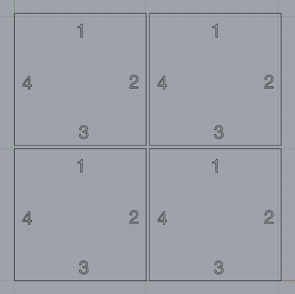
Create a cut file with 4 squares of the same size laid out like this. The squares don’t have to be that large but 4" (100mm) is a good size. Leave enough space between the cut edges so the bit actually cuts each of the squares individually. I should have numbered the squares in the drawing to: A, B. C. D just to know which is which.
Once the cut is complete, simply align the squares up and push them together so there are no gaps. Swap squares, say A for C, and align them again. Also rotate 1, 2, 3, or 4 squares and align the edges. Each time looking for gaps in the edges. Do this swapping a few times or until you are confident there is a problem or not. If things are square, there will be no gaps. If there are gaps, you can, with a little brain power, figure out where the inconsistencies are.
You don’t have to machine the numbers into the squares, just pencil them on after they are cut.