Updated 7/17/25
Applies to both regular and braking motors.
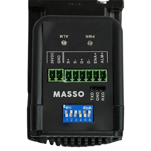
Wiring diagram
- 36VDC = Positive Power - Red Wire
- GND = Ground Power - Black Wire
- S+ = Step Positive - Yellow Wire
- S- = Step Negative - Orange Wire
- D+ = Direction Positive - Gray Wire
- D- = Direction Negative - Black Wire
- ENA+ = Enable - Green Wire
- ALM+ = Alarm - Purple Wire
Dip Switch Location:
Dip switches are the white switches numbered 1-6 in the blue portion of the motor.
Dip Switch 1 is Down/Off
Dip Switch 2 is On/Up
Dip Switch 3 is On/Up
Dip Switch 4 is Down/Off
Dip Switch 5 is Down/Off
Dip Switch 6 is On/Up
Switch 1-4 adjust resolution.
Switch 5 is the rising or falling of the clock edge of the step signal.
Switch 6 is motor direction.
Replacing Motor Video:
Tech Specs:
MASSO 36V
Closed-Loop Stepper Motor Specifications
Frame size: NEMA #23
Shaft: 8mm (.315")
Input Voltage: 36V DC
Output Current: 4.5A 20 KHz PWM
Pulses/Revolution: 800
Maximum Torque: 1.2 Nm (Newton meters)
12.236 kg/cm (kilogram centimeter)
169.934 oz/in (ounce inch)
10.62 in/lb (inch pound)
Torque Information
Stepper motors provide high torque at low RPM but as
the RPM increases the available torque reduces. The
below graph can be used for machine feed rate and torque
calculations.
Status LED & Alarms
The motors provide two visual indications of motor status.
A Green LED indicates that the motor is powered.
A Red LED indicates that the motor is in an alarm state.
Alarms can be caused by any of the below reasons:
• The enable signal of 5v to 24v is not received by the
motor.
• The motor received STEP signals that have acceleration
or top RPM higher than the motor can support. This
will also be affected by how much load is on the motor.
• The power applied to the motor is less or more than
the motor’s specifications.
• The current required to work under load is not enough.
• The motor is not able to complete requested rotation
due to external mechanical issues such as the machine
axis hitting something or getting stuck.


