I’m like a kid waiting for Christmas, counting down the days until my new machine arrives. I’ll post more pictures when completed including the internal electronics cabinet which is still a work in progress.
I very much like the cleanliness and efficiency of your table design. The stability and overall mass of the table will be an asset as well. Which V/A monitors did you decide to buy for the two applications?
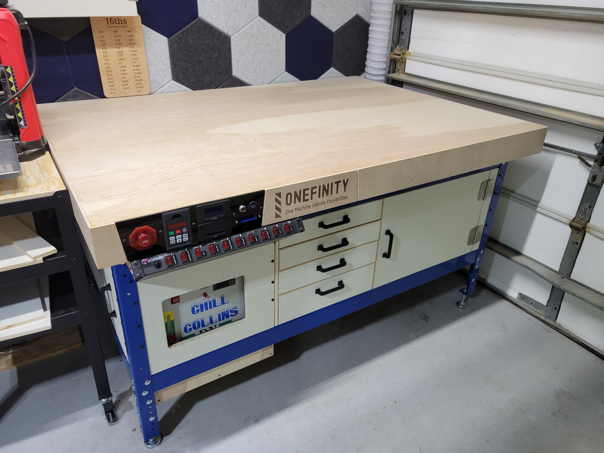
You are ready to roll! The table top is very nice and should be stiff and flat, both necessary attributes in my book.
Your post has generated a few questions for me:
The CW5000 cooler should do a great job. I am assuming that the refrigerant cycle cuts on and off on coolant temperature. Is that correct? As you know, many folks are using a bucket/pump as a heat sink and that seems to suffice so your setup should be as good as it gets relative to cooling.
How are you integrating the external remote E Stop with the controller? Is it as simple as using a couple of pins off the breakout board? I want to add one to my setup. I have found that fumbling around with the touchscreen in an emergency is not as quick as I want.
What spindle and VFD have you chosen? From the remote VFD display, I am assuming the VFD is a HY. Are you also planning to use a HY spindle?
Are you planning to use the RS485/Modbus from the OF controller to start/stop and set speed on the spindle? If yes, what will you use the potentiometer on the VFD’s remote display for?
Did you consider using the remote VFD display to display VFD current output vs. adding the two transformers? I am assuming that the HY VFD has function settings for that.
Look forward to more details as you move this along. Thanks for the interesting post.
These are the items I picked up. I have nearly identical units on my incoming house lines that were originally installed for monitoring generator usage during hurricane season. They are still going strong after roughly 5 years.
Yes, that’s the general idea. It works to keep the temperature below a certain threshold but is not cold by any means. The factory setting is 28°C (82.4°F). It should not need to work very hard for this application. I’m only using it because I already have it. I probably would not have splurged otherwise when the bucket/pump would likely suffice.
Yes, that’s my understanding. Pin 23 on the breakout board is for E-stop. The buildbotics manual shows values of NO (normally open) and VIL (logic input low) which I interpret as meaning the second connection is to ground.
I have opted to start out with the HY 2.2kW 80mm spindle and VFD, 110V model. We will see if I regret the decision of 110V later, but it will have its own 20A circuit. I do not currently have a 220V option in my garage and the breaker panel is already full unless I get creative.
Additionally, I special ordered the VFD for the ability to use a braking resistor to quickly slow the spindle.
Yes, I plan to leave start/stop/speed up to the gcode/controller. I don’t plan to use the VFD display for much else than being able to verify it’s at the correct speed.
I did not realize that was an option. However, I definitely want to be able to see and verify the spindle speed per the VFD display, so I am happy with the current configuration. And the current transformers offer some addition information.
Ref. speed display
Keep in mind that the touchscreen and Web Interface displays show speed. The Modbus picks that up and it is real time speed. You can see it accelerate when you turn the spindle on. I also checked the accuracy with a tachometer.
Ref. braking resistor
Some VFDs have the ability to stop a 2.2 kw spindle fairly quickly without it. I am familiar with Hitachi and have no actual experience with HY. My Hitachi can stop the spindle on my 2.2 kw spindle quickly enough without an external resistor. There is a specific function that is set for that.
The rotating mass on a high speed spindle is not that great and easier to stop than a regular induction motor. From my research earlier, I believe that the standard HY VFD offering may not have the capability to add a separate braking resistor. I remember seeing a note that you had to special order that. Again, I have no actual experience with HY but did a lot of research on them before buying a VFD for my spindle setup.
Ideally, I would prefer to have the unit in hand and be able to see and experiment with all of the capabilities up front to see what works best for me. But with the current production and shipping delays, I wanted to get a head start. I can always fire a new instrument panel out of acrylic on the CO2 laser if I decide to change things up (add/remove features) down the road.
This will also be my first “real” spindle, so I’m still learning there as well. My other machines, a V1 LowRider2 and a V1 MPCNC Primo, are running Dewalt 611 and Makita RT0701 routers respectively.
Cooling system is nice but may be overkill. I have a closed loop hooked yo a pc cooling 2 fan radiator and a reservoir/pump. I ran a 1 hour cut and it barely registered a temperature change(2 degrees in a 50 degree garage). Only holds 1qt of fluid.
The remote vfd display is nice. I use mine to confirm im up to speed, also it puts your vfd in a place it shouldnt pick up as much dust.
For sure, overkill. But I already have the chiller and it was collecting dust. It also gets very hot here (FL) and my garage is not climate controlled, so it will be nice to have a bit of active cooling for much of the year.
Wow! What a great example you’ve shared with the community. Very nice setup!
I was wondering if you’d comment how everything is hooked up to run? From the picture, it appears you have a control panel ready to go. How do you plan to wire everything?
I’ve chatted with a couple guys from this forum regarding electrical and they provided some great leads, examples and advice. I’ve researched this topic and continue to seek examples and ideas. I have your spindle and VFD, but the 220 version.
Thanks again for sharing your experience on your journey so far.
My plan is to wire everything up (controller, VFD, etc.) in the left-side cabinet behind the chiller. I can access this area easily by rolling the adjacent cart out of the way. I will use raceways to tidy things up as best as possible. But without the actual machine and knowing how long to cut cables/hoses, I’ve reached a stopping point for now.
Some additional notes:
I will be making appropriate holes in the tabletop to bring cables and coolant lines through, but I am hesitant to do this until the machine actually arrives and I can put everything in its place.
Everything will be powered from the 10-outlet/switch PDU except the VFD/spindle. The VFD/spindle will have it’s own 20A circuit. However, I am using a basic USB brick (5V output) attached to a switched outlet on the PDU to trigger a solid-state relay and turn on the VFD/spindle. This keeps all of the power control in one place, instead of having to add a separate heavy-duty 20A switch for the VFD/spindle.
I am going to be using the popular drag chain modification shown by others and have already printed the necessary parts, including the modified parts needed for the X-50. - Original drag chain parts - X-50 modified parts
I purchased 25ft of 14/04 shielded DriveFlex cable from Platt at $2.65/foot to run the spindle. I had issues with backorders when trying some of the other recommended suppliers found on this forum, but this arrived quickly.
Not previously mentioned, but I will also be adding an air-assist line in case I want to machine aluminum. I picked up a hefty 102W pump that will also reside in the left cabinet. It’s quieter than expected, but moves an impressive amount of air, and I doubt I will notice it inside the cabinet. And I can always upgrade to an actual compressor down the road if needed.
And I will be running a 4" exhaust fan inside the cabinet to reduce any heat build-up.
I ran my 3/8 x 1/2 tubing, 14/4 shielded , and stepper wiring through the drag chain. It was very full what size lines are you running on the water cooling. Depending on what size air lines you run may not fit.
Also I ran into an issue running everything off 1 switched power strip. The issue was The monitor started at the same time as the controller and would have to be restarted a few times for it to work. The solution was to keep monitor powered always and use its switch to turn it on a few seconds before energizing everything else. since I havent had any issues.
One of the items I power with the strip is a rib relay that opens an ivac dust port. Once ready to run I manually turn on DC though.
I am aware I will likely need to make adjustments, as well as possibly create and print new parts, to deal with the air line once I receive everything. But until I have the machine, I’m stuck waiting. But I think the tube which came with the VFD is only 8mm OD — I got some extra.
Each outlet on the PDU is individually switched rather than all at once, so different devices can be turned on independently.
However, I’m planning to mount a laptop on an arm, so I’m not sure the monitor will be an issue. I am used to being able to see the toolpath preview, which from what I understand is not possible on the monitor alone.
One of the projects I have planned is actually automatic/motorized dust ports. I already bought the linear actuators I need to make my own. My dust collector and a separate shop vac are currently controlled by remote controls which I have hung around the shop, but I would love to automate this. I will be using a 4" connection to the dust collector for the Onefinity
You might have some difficulty getting the14AWG in the cups/snug fit. I used 16/4 shielded and the 16 was a good fit… Of course I am running the 220 version, so 16 was more than enough for the amperage…
I did enjoy all these little obstacles setting up my machine. Because I hung it and went with a water cooled spindle and had to learn how cnc machines work all at the same time the little things that slowed me down were good learning experiences.
The 8mm should give you more room. Mine was 13 od so I had a hard time closing the drag chain on it.
It came! Been setting things up a little at a time over the past few days. There are still a few things to do, but we are officially ready to get dirty. Now I just need a project…
Much thanks. It has been a long journey, even since the photos above. I added two tool chests, which took nearly 4 months to arrive, to the back wall that also serve as a tool stand for a number of devices that needed more permanent homes. This has been the year of waiting for everything with shipping delays, so I’ve had more time to focus on shop organization, dust collection, and wood storage.
I still have plans to attempt to put together some fully-automated blast gates, which you remind me I should get to work on!