I’m looking to add ~4" in height to the machine. Not Z-height, but looking to get the whole thing up a little more off a (theoretical) fixture plate. I have some fixture ideas which don’t need to be reachable by the machine, or even I’d prefer it to be physically impossible for the machine to hit it, so to maximize the range of the already limited Z-height I want to get the whole thing raised.
I did a quick model of 4" blocks, and it seems like that’s enough. I’m a little worried about stability, especially in motion. I’m currently thinking these are bolt through, so 4 bolts into clearance holes and the whole thing gets rigid with the base plate. I could also key it into the slight dovetail on the feet. This might make it a bit more rigid since the load isn’t pure friction.
I would consider running the block the full distance of the Y axis to give it more stability. Also, you could extend the width to be larger to the outside to increase the footprint a little more.
I certainly don’t see why that wouldn’t work, as long as the Z axis can reach what you need it to. I don’t know that it would be necessary to engage the angled bottom of the feet, but it wouldn’t hurt. Using 8mm or 5/16" thru bolts, I doubt you’d have any stability issues.
It’s going to be pretty tall, and if you use 4" risers, that means a ‘normal’ job on the machine would need to be raised up that much or more. You may or may not wish to keep the risers there all the time, depending on how often you really need them. Otherwise they may prove to be a pain to work with.
I originally was worried about the limited Z height, and set my machine up on .75" risers on day 1. However, I ran into more issues with reach with the stuff I was making than I did with limited Z height.
After using the machine for about 6 months, I took them away and mounted direct to my table top. They are easy enough to add back in the future, but outside of using the machine with a rotary axis I don’t see needing the additional height. .75" is far from the 4" blocks you are talking about, however I don’t see 4" being an issue if you have something particular that you intend to machine and know you need that amount of space. You could do a runout test using a dial indicator once you get it setup, but again I doubt you will notice a difference.
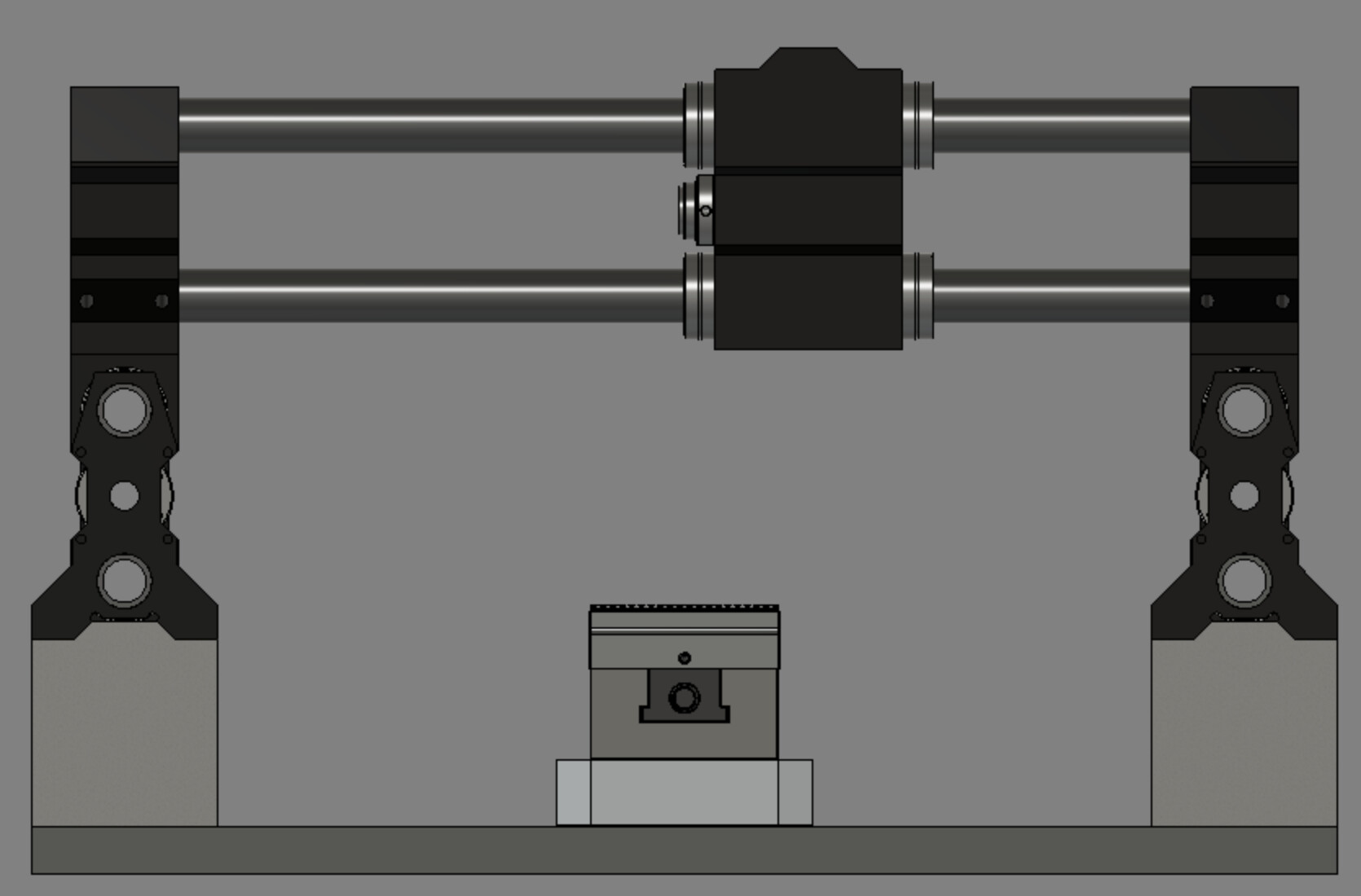
I modeled up a small interface and will check the feet on my machine. If someone has canonical specs they can share that would be great. I’m trying to get better measurements into the model so I can lay out the work envelop a bit better. As an example of this, I need to check the Z-plate hole spacing. I can probably move that up and get some additional clearance there and make the blocks shorter in height (lower cost, less offset distance, etc.)
I threw an example of a vise + locating plate into the picture to add more context. The locating plate is ~1.44" tall already, plus the vise. If I put a block of aluminum on the locating plate with 4" riser blocks I’m only -0.625" underneath to the feet. So I can go measure whether that gives me enough room to do some of the fixtures ideas I would like to do.
I would just look on ebay or somewhere like that and pick up some aluminum blocks. It would be easy to drill and tap holes to make sure the 1f was securely mounted to the block and the block is securely mounted to the table. I would hole that any table you make would have lots of support under each leg to begin with.
Bolt to 2x4s together and cut to a length that is wider than your table. Stack your machine feet on whatever sturdy blocks you have. Take those 2x4s that you made on edge and lay them across the tops of the feet. Using the best clamps you got put pressure on each of the feet from the outside. For all but the roughest and toughest cuts this should be easy hold down. This was my plan for doing large mobile services such as dining room tables or large slabs. Set up the machine directly on the workpiece or with some MDF underneath and then use the 2x4s and clamps to put pressures on the corner after lining everything up. Be careful about running the machine too far forward and hitting the 2x4 that passes across the front. You can set up the limit so that it’s not an issue. I hope all that makes sense
A friend and I were actually talking about this very subject with his Onefinity table needs. What we came up with was an aluminum extrusion frame on which the Onefinity would sit and in the center of this frame would sit an adjustable electric table lifting column. Then attach your table surface to this lift column and voila! You have yourself a drop table. Below is a photo showing an example of such a lift as well as some specs. Found this puppy for $99 on eBay.
Without commenting on the adjustable electric table, I think this makes a lot of sense. I priced out some very rough 8020 extrusion (80x160 for the height) and got a rough ~$375 ballpark for extrusion only, no fasteners, plates, screws, cut charges, shipping, etc. With this in mind, and considering I would still need a base fixture plate, I tried to think about what I could do a little simpler to put some distance between the machine and the plate.
On the dropped table center / adjustable movement, I have the same concern as @Hermsen.BJ: How would I keep everything square and flat without losing rigidity?
The telescoping device would not offer the necessary precision or rigidity in and of itself. There would have to be a means of precision locating & locking the table into position.
Bill is right. The lifting column would just be creating your lift adjustment. As with all hobby CNC machines (and I don’t even trust the professional ones) flatness doesn’t come from the table, (although that would be nice) rather it comes from the fixturing. This is why most people using MDF will surface it before setting work pieces on it. As far as rigidity of the column itself, talk to the manufacturer of the column you are looking at. For my friend’s needs, it works just fine.
Or do you mean the table (e.g. t-slot) vs. fixtures (something on the t-slots which is dialed in to be square/flat/parallel to the head)?
Yes.
Also if you’re looking for a way to mount the column, below is a very rough photo on how you might make it work. Your Onefinity Y axis rails would sit on the left and right sides. Then you would just mount you surface to the column. Roughly speaking, it should be accurate enough for wood. For high tolerances you would consider your fixturing.
I’m currently working on a lot of Delrin and plan to run some aluminum. The part I’m planning to run tonight has an o-ring groove, so I would like to be more accurate if I can
I’ve been thinking of a lift mechanism that works like on the DeWalt DW735 and other similar lunchbox planers. Four posts all meshed with a single drive chain. If you have another axis on the controller you could control the table height from there… Or just do manually and get a DRO to attach to the plate and monitor it’s height from there. I think iGaging Pro has a model that would work.
Agree with the 4 posts solution. 4 acme screws on four corners fixed to base and to same surface Onefinity it’s mounted. Table would be connected to 4 ball nuts. All screws turn at same time. If you built a Ridgid square to good the table it could be done.
In do have the riser blocks and have used them twice with no issues.