I don’t use VCarve, but generally the toolpaths generated by CAM programs aren’t tied to any specific location in your machine (they’re in an abstract work coordinate system, not absolute machine coordinates). In the controller, you should be able to zero the origin of your work coordinate system at whatever offset you need in X to avoid collision. The code produced by VCarve sees this location as (0,0).
You’re welcome to clarify if I’m misunderstanding the problem.
You can tile without using the tile toolpath option in Vcarve.
It requires more work but can be achieved by creating layers and boxes and toolpathing each layer
Now that is an interesting thought. I can’t see how setting project to a different X,Y origin than your machine and expect the g-code to find your project. Maybe I am missing something in your message.
The project doesn’t care what your machine’s home coordinates are. The project only cares about the project’s “home" or datum coordinates. The project is being located in a 3D plane defined by their offset from the machine’s home coordinates which define a specific physical point, typically lower left or upper right corner depending on the machine.
As long as your project’s datum is in the machine’s available 3D space and the project’s boundaries don’t exceed the available machine space then the project runs.
With the OF the machine 0,0 is lower left and some number of inches above the machine’s feet based on the Z gantry you have. So there’s a space approximately 48x48x5" (Foreman) extending out from approximately the machine’s foot that is the available workspace.
If you define the project’s workspace to be 2" inward (toward the right side on the X axis) and 1” back from the machine’s 0 point your project 0,0 is mapped by the software to the machine’s X2,Y1 position. This offset is stored in variables used to define the work’s coordinate system. Your project can’t exceed 46x47 in this case because your machine’s physical limits will prevent the movement past its rails. The same is true of the Z axis except since the machine’s Z0 is defined several inches above your machine at the limit of the Z axis upward travel, your Z’s work coordinates are expressed as negative offsets from the machine’s Z0.
All of your project’s movements are calculated by the software relative to the project’s axis offset from the machine’s physical home position. That’s why your first step when turning on the machine is to home it. That tells the software where the machine is in space. When you load a project you set the XYZ zero to where you have your project material placed within the machine’s space. If you don’t set a project XYZ zero it assumes no offset from the machine zero.
Tiling is simply a process in the software that tells it where slices of the project lie in the Y axis plane. Offsetting your starting position only affects where the slices are made so as not to exceed the machine’s physical boundaries. Each slice effectively gets its own Y0 starting point based on the project’s offset from the machine’s home 0,0 and calculated from the project’s Y0.
So for a project whose starting point is machine X1,Y2 and it’s 96” long, you’ll get 3 slices of 46" each (due to starting 2” back from the machine’s front reach). So your project’s 48" is actually the 2nd slice, 2” from the front edge of the slice and 4" back from the front of the machine. Your project’s tiles will be 46, 46 and 4" by whatever your project width is. All handled by the magic of the software.
I hope that was what your question was asking. Otherwise you just got a repetition of tile handling you already know
Thanks for taking the time to provide this detailed explanation!!
My spoil board is mapped in a grid pattern and I typically set an XY Datum Position and set my X and Y coordinates to indicate the exact location of my project.
To understand your method would I not choose this option? Would I mount the project in my chosen position and then X,Y probe the location to establish my 0,0 starting position.
Would I still get this message; “Toolpath Tiling can only be used on jobs with the X,Y origin set to the bottom left corner”. In my understanding this method would still be in the “bottom left corner”, just not the physical “bottom left corner” of my 1F.
I may not have mentioned that my 1F is wall mounted and using the Probe on a vertical project isn’t as handy as when you 1F is bench-mounted. This is why I use the XY Datum Position option.
Correct. Using the material’s bottom left corner as your datum, 0,0 is right. When Vectric is referring to needing it to be bottom left, it’s saying you can’t set the datum to one of the other corners or center which are other commonly used datums.
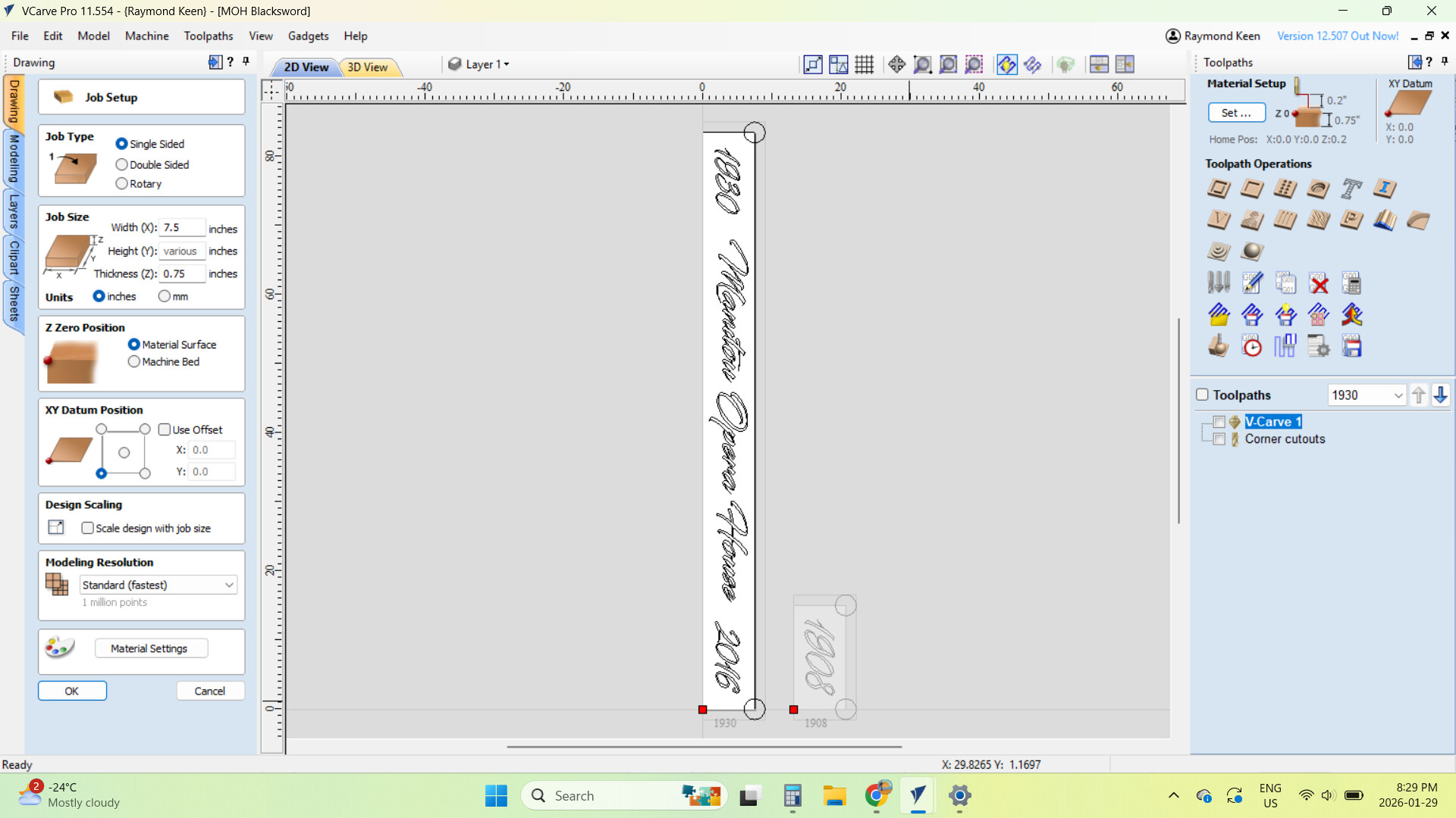
This screen shot will TILE as no XY Datum Position has been set, and the project sits at 0,0 on the 1F Spoil Board.
The next screen shot with a XY Datum Position of X20, Y0, will not TILE and creates the error message.
Are we on the same page?
As we talked about earlier, I could position my project on the 1F Spoil Board (without an XY Datum Position) and then use the XYZ Probe to set the physical position of the project on the Spoil Board. Is this the workaround? Will this setup TILE?
Leave the origin at the bottom left 0,0 in VCarve like it wants you to. Put your workpiece wherever you need to, it sounds like that’s X>=20. Then, either probe or manually zero your machine at the bottom left corner of your workpiece. That’s all you have to do. Every tiling operation will start from that same zero position as long as you don’t lose the zero by restarting/rehoming the machine (not sure what controller you’re using). Between operations, you just need to make sure that you’re shifting your workpiece by the right distance and keeping it parallel to the Y axis.
No. What we’re trying to do is tell the machine where the project thinks 0,0 is. So in VCarve your datum is 0,0 but on the machine you move it to X20,Y0 and then hit the Zero All (or zero each axis and you’ll need to set Z zero separately) or use the probe to zero all.
Now when the software says to the machine, go to 0,0 it will go to machine 20,0. As far as the software is concerned, that’s 0,0 - it doesn’t know anything about any space to the left. (Technically, you could go to X-20 and it would move to the left because there’s enough room on the machine’s plane to do that, but X-30 would throw an error because that would be a machine coordinate of X-10 and the X can’t be negative for the machine.) In G-code terms you’re setting a Work Coordinate System (WCS) variable that the controller will then use to translate movement commands to map to physical machine locations.
You change the datum in VCarve to specific coordinates as a way to avoid having to zero your X & Y because you’re going to use machine coordinates instead of work coordinates. You might have a jig that you use, or a grid in your waste board that you use to align your project material to. Then all you have to do is zero your Z and just swap out pieces of project material. It makes for faster production work.
@xenith has a good explanation as well which might be clearer for you than mine
I have to say that once you get used to always setting an XY Datum Position I wasn’t accustomed to using the XYZ probe for anything other than my Z position.
My Onefinity is wall mounted so the usual way of using a Probe doesn’t work to well.
Now I will use a V bit to pinpoint my exact X and Y position to start my Tiling Toolpath.
Thanks everyone for helping me past this setup challenge.
Assuming your material’s physical lower left corner is where you want your project’s 0,0 to be, you can screw in a piece of wood whose right side lines up with X20. Then you can just push the material up against it. That gives you the repeatable X position. Then if you score a line at Y0 on your waste board you can line up the bottom (& subsequent tile sections) of your material and use the MDI window to execute a G0 X20,Y0 and then use the set zero buttons in the control software to set your project’s 0,0. No need for the V-bit for setting X & Y zero and just use the probe for Z with the actual cutting bit you’re using as you have been doing.
You can also line up the bottom edge of the piece of wood that you’re using as a left edge stop so it’s aligned with the machine’s Y0 and just align your workpiece with the bottom edge as well. Assuming your waste board is longer than your machine’s Y axis, you can also make yourself a Y positioning jig out of a piece of wood with a lip on the bottom so you can just slide it on to the waste board to create the initial bottom stop for your material.
As you get more experience, you can start to think about how your workpiece can also be something your VCarve project is mapped to. The left edge of your VCarve design doesn’t need to match the physical left edge of your material for example. You can think of it as layers - the machine’s actual physical area is the lowest layer, the project material is the next layer and the design is the top layer. Then by how you place the material and how you set your 0,0 you can “float" your project onto the project material wherever you want. That way you can reuse a design on different sizes of physical material stock without having to create a new VCarve file for different sized stock. You just set your 0,0 at the machine based on where you want your design to land on the material. I do this to allow me to use the same design file for an engraving on different sizes of cutting boards without having to have a different project file for an 18x12 board and another one for a 22x14 board.