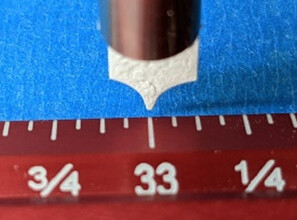
While verifying operation of my new Journeyman, I discovered that the Y-axes have a substantial amount of differential travel. After homing, when I move the Y-axis by its nominal full-travel distance, the ball nut on my left Y-rail travels about 1/64” farther than the one on the right rail. Over the 32” of Y-axis travel, that’s about one part in 2000. This is not a mechanical defect, per se, as this much lead error is well within the tolerance of economical ball screws.
The average lead error of each Y-axis ball screw would quite easy to correct in software, except that the control software automatically disables editing of the “travel-per-rev” parameter for a slave axis. In effect, the software is saying “I’ll let you set the nominal pitch of the ball screws, but I won’t let you make independent adjustments for ball screw lead error when there’s a slave axis involved.”
For woodworking applications such as sign-making, 1/64” of Y-axis positioning error would probably never even be noticed. But here are some use cases where the differential-travel error presents a real problem:
- If I attempt to mill a rectangular workpiece, the front and rear edges of the workpiece won’t be parallel.
- Edge joinery that is milled along the Y-axis (e.g. modified box/tab joints), won’t fit together properly unless both mating edges are milled at approximately the same X-axis position.
- When tiling full-width workpieces, milled features will have a gap or overlap of almost 1/64” at one side or the other.
- When flipping a workpiece over to mill features on its back side, those features will generally be misaligned with the front-side features.
So here’s my specific feature request: Please modify the controller software so that users can edit the “travel-per-rev” parameter independently for slave axes. That would make a dramatic improvement in the achievable accuracy of Onefinity machines.


