That’s half as loud. A huge difference. Especially since 70 is something like a vacuum cleaner and 80 is loud enough to cause hearing damage over long periods (like a day’s use).
I already have a 30 gal. barrel to use so don’t need the 13 gallon one included with the DD XL. I have the Super DD on my DC in the shop and it works very well. For the CNC I wanted to try something different so I got the Jet.
There is no way I could put up with a shop vac running for hours on end. It would drive everyone in the house crazy even if I was in the garage. I could use my CT-36 as I said. It is very quiet and has plenty of power. But I see that as a waste of a good piece of equipment. I’ll save my CTs for sanding and use with my power tools.
10dB IS a huge difference.
- 3dB roughly doubles (1.995) the sound level.
- 6dB is about 4 times (3.981x) louder
+10dB (70 to 80dB) is 10x louder
85dB is the point where you need hearing protection per OSHA
and NIOSH, but it certainly doesn’t hurt to wear it at lower levels.
I don’t use a meter to tell me when to wear hearing protection.
If I am running a power tool in the shop I have ear plug or muffs
on. and whenever I am using yard tools or the mower I wear muffs
because they are more effective than ear plugs.
If you have an iOS phone the CDC has an app that they claim works very well with an external mic. Info on the app and noise levels can be found here.
https://www.cdc.gov/nceh/hearing_loss/what_noises_cause_hearing_loss.html
My Kreg 44" x 64" bench parts arrived this afternoon and about one hour later I had it assembled and roughly leveled. Once I get it in its final position, I will level it again. Level and flat are not always the same thing I understand but I think it’s easier to work from a level AND flat surface when you can. Right now, the top of the frame is 33.5" AFF.
Next is building the table top.

I’ve been thinking about rotating the table 90 degrees to put the side against the wall and not the back. That way if I need to tile something I don’t have to move the table as I will have about 4 feet behind the table in which I could set up a couple support stand to hold the end of a full sheet of plywood. I would then have access to the back at all times with no hassle and be able to reach in from the front or back to access the left side if need be since the table will only be about 50 inches deep in that direction. That sounds easier than trying to reach in 3 feet or more from the side.
If I wanted to leave it in the orientation it is now but pull it out from the wall 4 feet I don’t have enough room to do that. I also think that rotating 90 deg would help with running the power and dust collection hose.
Edit: I guess this post needs a photo.

I did go ahead and rotate the table as I discussed above. So now I can feed a full or half sheet of plywood through if I needed to. I doubt it would happen often (if ever), but I am setup for it now.
I got the MDF for my QCW waste board cut and installed yesterday. I made the counterbores .625" (5/8") which is more than large enough for the washers shipped with the QCW frame.
Still learning about this thing so a lot of questions. Here’s a few.
1.) I noticed that the machine after booting up and I run the Homing routine makes a noise. A slight hum I will call it. It sounds like a low-level current is being applied to the X and/or Y motors. Not enough to move them though.
If I manually bump the joystick in the X or Y direction I can make it go away most times. It seems that it is in both directions (X and Y) and I have to find the happy spot where both are quiet.
It’s not so loud that it is an annoyance. I am more concerned if it is bad for the drivers to be pushing out that low current whenever the machine is idle. It will do it endlessly unless I find that sweet spot where it stops. If I move the spindle from that position any time after the hum will start up again. It is not one specific location (X,Y) that is free of the noise. It could be any place withing the boundaries of the machine.
2.) The joystick is making me crazy. Most times when it powers down from inactivity and I wake it up the mode has changed. Is there a way to lock it into the mode that is compatible with the Onefinity controller?
3.) When I first installed the Z axis I put it in the middle of the three elevation choices. I think that was the recommendation but not sure. Anyway, with the QCW if you use the middle position it is possible to lower Z to the point where your bit is well below the MDF and into the tubes by a good 1/4". I know I can raise my bit in the collet but it’s inserted almost all the way now. Could maybe go another 1/4" but that won’t be enough to keep the bit from contacting the frame if something goes wrong and Z is trying to drill a hole through the table to China. 
To avoid this I moved the Z axis up to the highest of the three bolt hole positions. The bit can still reach the top of the MDF waste board and will be able to cut completely through a workpiece, so I think this is OK but interested in what others have done that have the QCW.
I’d rather have the machine physically setup so it can’t self-destruct. I don’t like to put too much faith in software.
I have noticed the same thing with mine it sounds like stepper motors are trying to move I just bump it a bit with the joystic
Yes that clears it up but should I have to do that?
Big picture is can it do any harm to the drivers or the motors to be sitting there with that idle current applied. It consumes power for which you get no work and you’ve got your driver boards in use so you are aging the components and again getting no production or use from them for that idle time.
Does the controller software have a time out where the drivers are shut down after x number of minutes of inactivity? I understand the need for idle current (depending on the motor used). Just wondering if the Onefinity stepper drivers are programmed to shut down and if so what the time is because after 15 minutes mine are still running. And if they were programmed to shut down then giving it that bump should not cause the idle current to be reduced to zero. If anything bumping should reset the clock on the inactivity timer to zero.
Or is it because the motor has stopped on a micro-step so the driver is applying current to hold it in that position.
You may have your QCW frame and leveling feet by now, but for others I will say get the leveling feet so you can level the frame precisely.
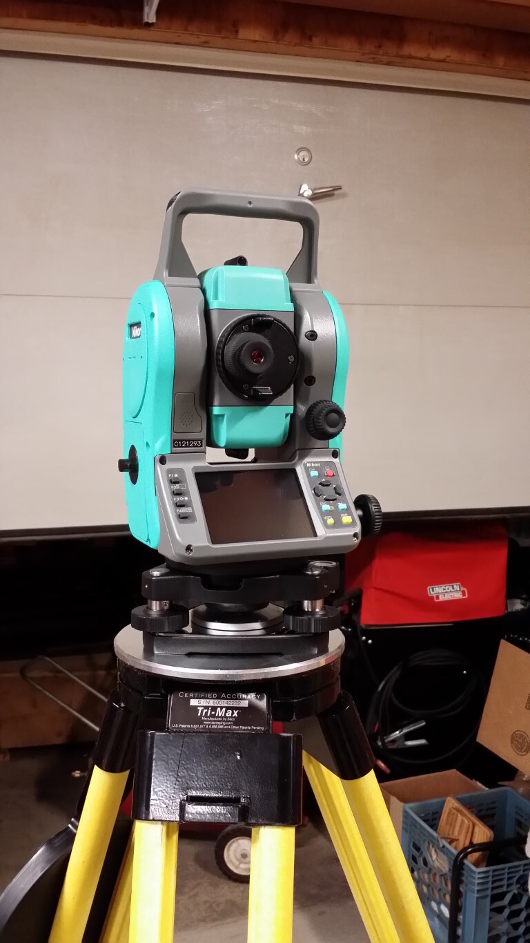
I leveled my Kreg table to within 1/32" (.031"). Then assembled the QCW frame on top of that and used my Nikon Total Station to adjust the leveling feet and bring all four corners within 0.010". From there leveling the wasteboard surface should be easy.
I wish the leveling feet had half-height lock nuts or there was a grub screw you could tighten to lock the foot adjustment in once you have it dialed in. If you slide the whole machine around on your table top you could inadvertently rotate one or more feet and given the coarse thread (I’m guessing the screws are 1/2"-13 thread) on the leveling feet a quarter turn is probably ~0.15".
Thanks for letting me know I’m not the only one who noticed this. I don’t know if anything is wrong, just seems odd for the gantry to sit there idle while pumping amps out to three stepper motors telling them to do nothing.
If that’s OK and does no harm then good.
The stepper motors have current run to them when idle. This is idle holding current.
Thank you. Now I know not to worry about this condition.
I’ve had my machine setup for a couple days now. Made a few test cuts and now it’s time to flatten the spoilboard and get the whole machine dialed in as best I can.
I wanted to have an idea where I was starting at so I stuck a digital indicator in the collet and zeroed it out at 0,0 then zeroed Z with the indicator in the middle of its travel. The indicator is direct reading to 0.01mm
I took 9 readings spaced around the board. I know given the board is 48 x 32 inches there are big gaps between those 9 readings, I just wanted to get an idea of how bad it is to start. The greatest difference of 0.22mm (0.0086") seems pretty good to me. I am thinking that once I verify the spindle is perpendicular to the table I can surface the spoilboard. Or do I need to surface it first. Seems like a chicken/egg situation to me.
Can’t make the surface flat with a spindle out of plumb and can’t get the spoilboard truly flat with a spindle that is not cutting flat. I have a 1.5 inch spoilboard bit.
Which should be done first and does it need to be repeated after the second step.
Or should I not even mess with the MDF in the QCW and lay another slab of MDF on top and flatten that.
Do you have a way of determining the angle of your spindle/tool relative to the spoil board without relying on the result of your surfacing bits cut? For example a smaller flat surface like a piece of glass and machinist squares that could be used to identify any tramming issues prior to surfacing.
Hey Bob,
if you are satisfied with coplanarity of table and QCW frame, which I would ensure first (and I know that you adjusted the other day) you can level the wasteboard. If your spindle axle is not perpendicular to the table you can level the wasteboard anyway, it will be leveled but you could have beautiful patterns from your flattening bit depending of amount of inclination of spindle 
or a mirror. Insert a smaller, not too short end mill bit into the collet and lower the Z until it practically touches the mirror. Prolongation of bit in its image in the mirror should have no kink (check with eyes from two sides which are 90° away from another, e.g. from front and from side)
Yes, that’s what I want to avoid, but I don’t see how. I either cut with an out-of-square bit or square the bit to a table that is not flat.
I think the thing to do for me since I feel the table is not perfect but pretty good now is:
1.) Square the spindle shaft to the table
2.) Flatten the table.
3.) Repeat the bit check to see if it needs tweaking to get it as close as I can.
I will try your mirror idea first then go from there.
If you flattened the wasteboard with an inclined spindle, the overall surface will still be plane. If the size of the reference object you put on the flattened surface is at least larger than two times the flattenening bit diameter, the object will be parallel to the overall surface - even if you have patterns (irregularities) from inclined spindle when flattening.
Yes, I could do that. I think I have a piece of 1/4" precision ground rod about 6 inches long I could place in the collet and work off of that.
I could set up a DI on the side of the rod then run Z up/down and check for any runout in the Y direction. Then repeat at 90 degrees in the X direction.
If you have dial indicator you can do it in different ways and you can do it with high accuracy.
I got the DTI out of the shop and will make up a map. But since I don’t have a 1/4" rod like I thought I did (it’s 3/8" and won’t fit the collet on the RoutER11) Will have to hold off for now unless I come up with something else I trust to be dead straight.