June 2026 Shop Update

Howdy.

Long time no see. My new job has kept me far too busy.

But recently I spent a bit of time in my shop, and made some upgrades to my setup that have me feeling all warm and fuzzy. Basically a “Felt pretty, might delete later” kind of post. So here’s my June 2026 shop update.
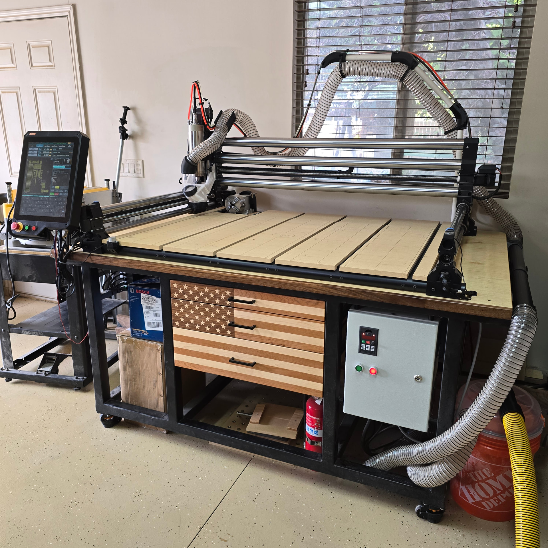
4th Axis

Just an Amazon special CNCTOPBAOS, hooked up with the old spare Masso Z motor that got replaced by the braking Z stepper. It was a quick conversion. Custom 3D printed belt cover to keep dust out.

Not totally sold on the placement in the back left corner. It doesn’t collide with the X-carriage, but it can collide with the spindle and dust boot. It also doesn’t give me a huge diameter to work with, even if I remove the left spoilboard slat. Luckily chess pieces are small, and that’s kinda all I wanna do.

First test on the 4th axis (using Autodesk Fusion 3+1 milling, 4th axis configured as my G59 offset):

Spoilboard

Spoilboard grid isn’t a new addition, but I don’t think I’ve shown it off before. Major gridlines every 100mm, minor every 25. V-groove numbers on the major. CNC center marked at (610, 408):

What do you all recommend for hold downs and datums? I’m thinking of adding dog holes, but that’s a major commitment and I just don’t think I’m emotionally ready.

Dust Collection

For dust collection, I’m still rocking the Hermes dust boot (shameless self-promotion), but I’ve upgraded my vacuum from a Ridgid banshee to the Dewalt Stealthsonic. Got it for $75 on a Costco special. It is remarkably quiet, but it also gets remarkably hot on long carves, so we’ll see how long she holds up.

The Stealthsonic came with two extension wands, which let me create my favorite addition to the setup, a removable inline, long-reach cleanup wand. While the CNC is running and the wand is stored, there’s suction at the boot. When it stops I can just remove the wand and clean up the table. It is ecstasy.

Organization

Finally organized my top drawer with some Kaizen foam. It was about dang time.

Put some QR codes on my endmills for easy reordering. But now I want to create a full Manufacturing Execution System.

CAD

Updated my CAD model with the changes. Also updated my post processor as well to work with the 4th axis. This way I can simulate CAM toolpaths with the machine model and be confident that it won’t crash.

That’s about it

Thanks for reading and viewing. Hope it gives you some inspiration. As always, I’d love to hear your thoughts.

Here’s a sneak peak of what I’m working on next. Should be ready in a month or two or seven, unless Masso shuts me down.

Check out ToolQuest’s new EdgeHugger™ clamps, currently available from IDC Woodcraft. They’re a real game-changer for CNC workholding, in my opinion. I’m a little biased, being the founder and president of ToolQuest, but a large majority of the reviewers on IDC’s EdgeHugger product page appear to agree with me.

For workpiece positioning on my own spoilboard, I use 5/16" dowel pins as miniature dogs. I machined an X-Y grid of 5/16 holes on 2" spacing, all of them bored for a precise fit to the dowel pins. You can see the hole grid in the photo below. I usually use long dowel pins and remove them after clamping the workpiece, but you can also use short dowel pins and leave them in place during machining.

I chose that particular photo mostly to show off my Hermes dust boot. This surfacing operation is an extreme use case for it, with the brushes overhanging the edges of the workpiece for much of the operation, and a 2" surfacing bit spinning at 18 kRPM, firing chips at a speed of about 100 MPH. It worked far better than my original Suck-It dust boot on this operation, capturing the vast majority of fine particles and keeping my machine much cleaner.

EdgeHugger clamps are typically placed on the top edges of workpieces. But that rough-sawn walnut blank was severely bowed and twisted, so I used tape and hot glue to attach it to a 1/4" MDF baseplate , and then clamped the baseplate to the spoilboard.

Back to the dowel pins, I use stainless steel so that I don’t have to worry about them corroding. 5/16" SS dowel pins cost a buck or two each from McMaster-Carr, depending on length. If you’re concerned about tool crashes, they’re also available in brass or aluminum, but at substantially higher prices.

That’s a nice setup. I ended up going down a very similar path after getting tired of spending more time figuring out how to hold a part than actually machining it.

What I found was that once I had repeatable locating points available across the machine, I started building fences, corner stops, and other fixtures that all referenced from the same hole pattern. Being able to remove a fixture, put it back later, and know it’s going to be in the same location has been a huge time saver for repeat jobs.

I also agree on the precision-fit dowel holes. Having accurate locating points across the table makes setup much faster than measuring and squaring everything in every time.

Looks like we came to the same conclusion: a grid of repeatable locating points is one of the most useful upgrades you can make to a CNC router.

These look interesting. Definitely going to have to fight the urge to reverse engineer a 3D-printable version.

That’s a beautiful setup. Makes me wish I wasn’t chained to the QCW. I’ll have to figure out a way to adapt it! Is that using your WoodAnchor system? Do you just full slot cut it with the CNC?

Okay filing this away for future use. I always just use super glue and painters tape directly on the wasteboard and then have a nightmare getting it free. Clamping a flexible backer makes way more sense!

Thanks for sharing! I love to see them out in the wild. What are you thinking so far? Any improvements you’d like to see?

Duly noted. I will be working on this ASAPsual. I also love the fine fixture plate wasteboard on the coarse fixture plate wasteboard. That would be great for periodic setups. Does it register in the bottom dog holes?

Those are some beautiful clamps! Are they your own design?

I also started with 3D-printed prototypes. Without going into too much detail, those won’t work for many common use cases, unless you also make custom clamp screws. Which I did, and it wasn’t much fun. The production version of the EdgeHugger clamp head is made possible by tooling costing tens of thousands of dollars, not counting the engineering time.

Yes, the T-slots are standard WoodAnchor fixturing slots. I was still using a Makita router as a spindle when I made that spoilboard, so I had Whiteside produce a batch of WoodAnchor slot-cutting bits with 1/4" and 8 mm shanks. With those new router bits, you first machine 1/2" wide rectangular slots, and then finish the profile with the WoodAnchor bits. With a 1/2" spindle, it’s possible to machine the entire slot with the original 1/2" shank WoodAnchor bit, but I still recommend preslotting an undersized rectanbgular groove. ToolQuest will have the new small-shank router bits and the M6 WoodAnchor nuts available for purchase very soon.

I think the Hermes design is absolutely brilliant. It greatly improved my dust collection efficiency.

My only real complaint is that my old 3D printer needed more generous fit clearances than you allowed in the STL files, so I had to do a lot of tedious hand-fitting. I’m accustomed to being able to compensate for printing tolerances in Fusion, but that wasn’t possible with complex STL files.

After getting some experience with the Hermes boot, and doing airflow measurements and calculations, what I’d really like is a version that’s fully compatible with a standard 3" diameter hose drop. An 80 mm view-portal tube would be perfect for that, and would visually match my spindle diameter. I believe there’s enough room to maintain that airway size all the way to the router bit. Per my calculations, with my 1200 cfm dust collector, all that would reduce the airflow restriction enough to roughly double the airflow as the brushes move off of the workpiece.

Would you be willing to share that file for the belt cover on the rotary? I have that exact model but mine is mounted in the front right corner so some protection would be nice.

File attached! It’s got storage for your chuck key. I will admit, printability ain’t great. It requires supports. Make sure you’ve got it mirrored the right way, I flipped the motor mount plate on mine.

And just double check before printing, this is the 4th axis I have: CNCTOPBAOS K12-100mm CNC Router Milling Machine Rotational Axis A 4th Axis Rotary Table 100mm 4 Jaw Chuck Dividing Head,MT2 65mm Tailstock Reducing Ratio 6:1 for CNC Engraving Machine - Amazon.com

4th Axis Cover.stl (237.7 KB)

Thank you! Printing now, will see how it goes.

Thanks! That’s exactly what I was after when I designed it. The larger plate stays on the machine, and then I can build dedicated fixtures that mount to it for repeat jobs.

Yes, it registers off the dowel holes. I use precision-fit dowel locations for positioning and the threaded holes for clamping. That lets me remove a fixture and reinstall it later without having to indicate everything back in.

The 5-part setup was actually one of the jobs that convinced me the concept was worth pursuing. Once the fixture was built, loading and unloading parts became much faster than setting each one up individually. I ended up developing the idea into a complete fixture plate system because I found myself using the same approach over and over again.

Thank you! Yes, they’re my own design. I made them because I wanted a simple way to clamp parts on a fixture plate while still having a repeatable locating system to build fixtures from.

The fixed rail locates from the dowel pattern, while the adjustable rail floats to accommodate different part sizes. In the 5-part setup shown, I still dialed each part in individually, but the fixture plate made it easy to build the fixture and keep everything organized and repeatable.

A lot of my fixturing ideas have come from trying to reduce setup time on small production runs and one-off jobs.

I’m impressed! Are the clamping elements Mitee-Bite Pitbull clamps? I’ve looked at those online, but never tried them.

Thank you! They are Mitee-Bite Pitbull clamps. I’ve had good luck with them. They generate a surprising amount of holding force for their size and work well for fixture plate applications because they pull the part down as they clamp.

The rails are my own design, but the actual clamping elements are standard Pitbulls. I wanted to use an off-the-shelf clamp that people were already familiar with and build the fixture system around it.

Looks like your belt is slightly shorter so my motor is mounted just far enough away it rubs :frowning: