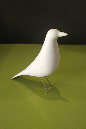
I knew as soon as my machine build was ready to be used that I would strive to make my version of the classic Eames House Bird. I thought it would be a great project because I like the aesthetic of the finished product, but more importantly that it would challenge my newly developing skills with F360 CAD and CAM. It took me a long time to get to this point, but I now have a system where I can accurately create these birds repeatedly, with results that meet my expectations.
Below is an overview of evolution of the project. I have included images of the CAD/CAM, work holding, components, machining, and a link to a video of the machining of the various tool paths for those interested. Please jump to end for links of the journey does not interest you ![]()
The design
There are many files on the Internet inspired by the Eames House Bird, but for me the challenge was to find a mesh model that had the highest poly count that did not crash F360 or overwork my mobile workstation. After that it was a matter of making a few changes until I had a model body I was happy with. I am limited to some degree in the tooling I can use with my ISO20 ER16 and ER20 holders and collets, so I scaled the model down to a size that allowed me to use regular length tooling with conservative stick out. The approximate stock size ended up being 200mmx100mmx50mm.
Here is a photo of the model with tabs I added to secure it during machining:
Two sided machining
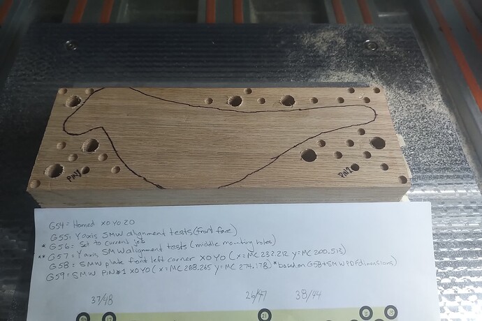
In order to accomplish the two sided machining, I used a locating pin method. I took advantage my M6 threaded fixture plate and the M6 locating pins I had purchased for it. I modeled the locations for the 2 pins and added them to my design. For machining the second side, the stock would be flipped over 180 degrees along the X axis, nd held in position using the pins - this resulted in a very accurate and repeatable locating method. NOTE: the origin for the top machining setup is the top bottom left of the stock, and changes to the centre of the left hand locating pin for the bottom machining setup.
Here are some photos showing the locating of the stock:
Workholding
My work holding strategy underwent changes from early testing to the final method I decided on. To test the work holding strength and repeatability, I initially used a tape method to hold the stock to a MDF board with holes drilled for the 2 locating pins. As mentioned earlier, I later switched to using 2 M6 locating pins on my aluminum fixture plate. Although the tape worked, I wanted an even more secure method - that also used less tape ![]() . After a lot of work, I ended up with a method whereby I drilled holes in the corners of the stock for 60mm M6 SHCSs, and these were screwed into the threaded holes in the fixture plate. To accomplish this I learned how to add the hole locations from my fixture plate CAD file to my bird file, and after a lot of trial and error determined the best locations for the 4 screws so they held the stock well during all machining steps but also did not collide with the end mill. It added time and effort but the result was what I wanted.
. After a lot of work, I ended up with a method whereby I drilled holes in the corners of the stock for 60mm M6 SHCSs, and these were screwed into the threaded holes in the fixture plate. To accomplish this I learned how to add the hole locations from my fixture plate CAD file to my bird file, and after a lot of trial and error determined the best locations for the 4 screws so they held the stock well during all machining steps but also did not collide with the end mill. It added time and effort but the result was what I wanted.
Here are photos of some of the earlier setups:
Toolpaths
I learned the most about F360 toolpaths on this project compared to what I had done to date. My success in the end was a result of many trips to the Autodesk forums for help, and a great deal of trial and error on practice stock. I won’t go through all the details of why I ended up with my current machining strategies - and as a beginner realize that there may be other better ways to machine this project - but here are the those that worked for me (NOTE: they are almost identical for the second side):
- An adaptive clearing toolpath with a 1/4" 2 flute endmill
- A contour toolpath with the same endmill
- A scallop toolpath with a 1/8" 2 flute ball nose endmill
- A contour toolpath with the same endmill
*This does not include the boring operations for the 2 locating pin holes and 4 M6 mounting holes
Here are some photos of the toolpaths:
Legs, eyes, and finishing
Placing the legs and eyes correctly was a big challenge and required me to further develop my F360 CAD skills. It took some creative problem solving but I was able to model the accurate locations for the legs and eyes, both were a challenge as they were at different angles on a model that was a completely organic shape. My original plan was to model and print a 3D jig that would allow me to drill holes for the eyes and legs. This worked perfectly for the legs - which I make from 1/8" stainless steel stock - but I did not like the way the eye holes turned out. To solve this I went back to CAD and modelled the eye sockets. It was a challenge but in the end worked out for the best as I can now easily modify the size of the socket depending on the eyes I buy and the size of bird I make. The eyes I prefer have the metal wire attached. I use a small drill to make a hole for the wire at the bottom of the eye socket, and after trimming the wire to length, insert it and glue it in place with CA glue.
Here are some photos of the leg drilling template and a few finished birds:
LINKS:
Outside of forums I am establishing myself as TMDesign
YT video link summarizing Eames House Bird machining:
My Instagram page(with link to my YT channel):
Thank you for your interest


