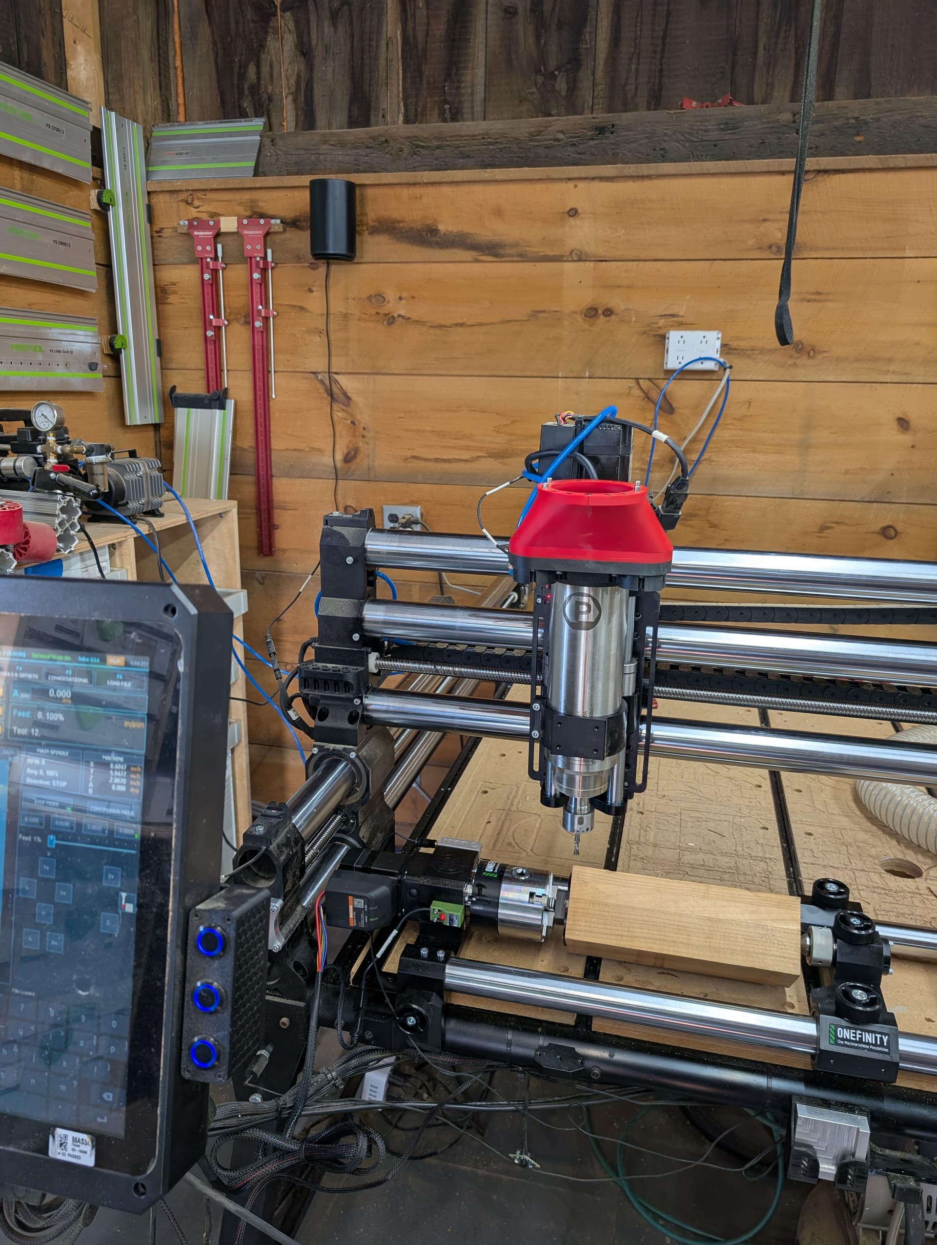
Hi, all. I installed my Revolution today and believe that I have it all set up correctly. I loaded a 3x3" blank into it and want to round it. I’m getting an X soft limit. Wondering if anyone could try to help me one step at a time to keep it simple. My ideal goal would be to round the center of this blank, leaving the ends, especially at the chuck, to avoid the screws.
Set the job to 2 inches less than the piece in the machine- 12" for a blank 16" long.
This way there is room for error and less chance of hitting the chuck or tailstock.
Set the job to the centre and Z zero from top of stock, there’s less chance of bits breaking
Like anything you have to practice with the unit to get a feel for how it behaves.
For instance I didn’t realize when the rounding toolpath runs, it takes off quadrants and returns, I thought in my head it would just constantly rotate and the spindle would just pass from Left to Right.
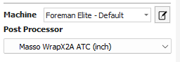
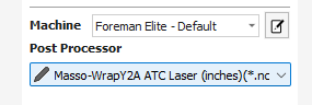
I believe the issue is with your post processor selection. The rotary is oriented along the X axis, BUT… the design you are carving is wrapped around the ‘Y’ axis (onto the A-axis). You need the ‘Y2A’ post processor, not the ‘X2A’. That is probably why you’re getting the alarm.
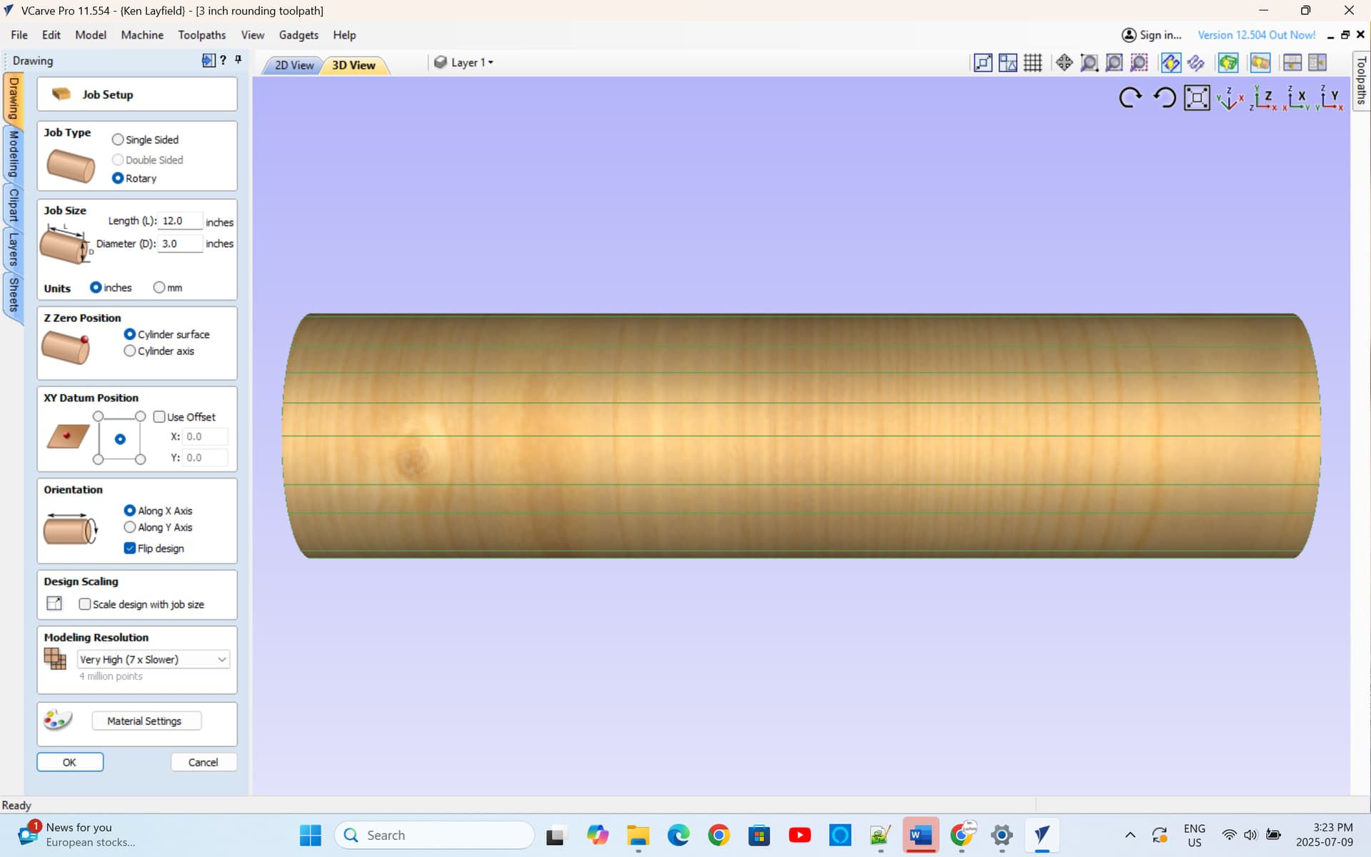
So your job setuo in Vcarve should look like this
Job is running in the y direction and on the left hand screen you have selected material surface
When I use my rotary, I manually set the job origin using the control panel jogging feature
Once I have jogged to the centre of the workpiece in X and Y ,I zero out X and Y.
Then I manually set Z zero with a piece of paper and manually jog down Z to the material surface and zero out the Z axis
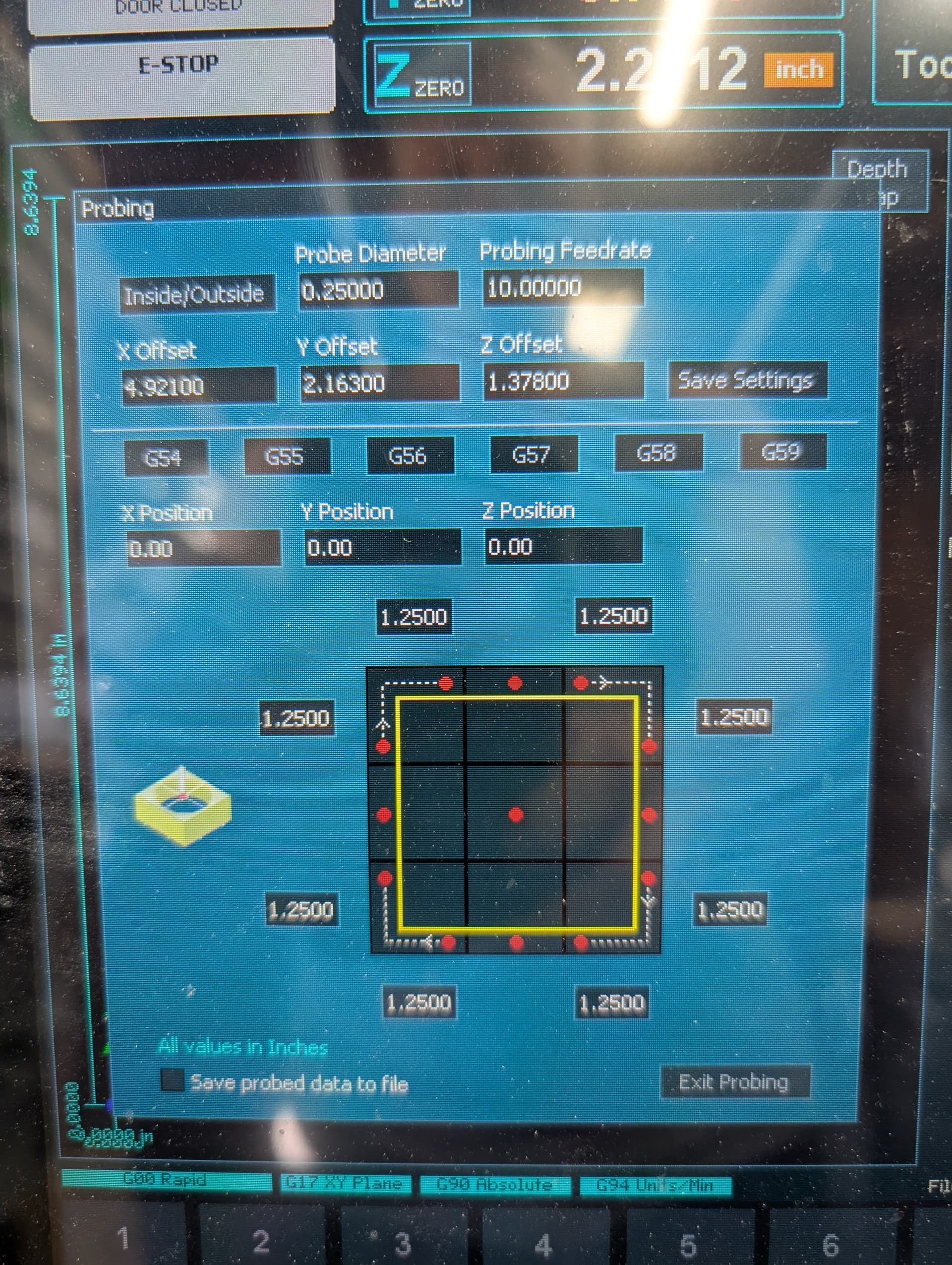
Ok. That explains a lot. I have been using the integrated zero block. I believe that I just figured out a stupid mistake that I was making. The integrated block is at the NW position, which didn’t match my job setup. I understand what you’re suggesting now.
When you set the Z on a BLOCK, do you set it to a flat side and it somehow knows how to deal with the corners, which will be higher when at TDC position?
So if you have a square block, setting off to a flat side will result in deep cuts on the corners.
The rounding toolpath in Vcarve allows for that and adjusts the cutting depth. It takes it off in quadrants so don’t be alarmed of its weird movements
To be on the safe side, set up the machine with an endmill installed then take it out before running the program. An “aircut” will allow you time to stop the machine before it does something stupid
How would you approach a second pass if the first didn’t fully round the stock? I’d rather not have it spend time cutting air. One problem that I had was that the piece, when mounted, wasn’t plumb in the A0 position, so I couldn’t properly zero the Z.
SO, I’ve done a half dozen passes/attempts to get this down to the intended size. By re-zeroing, it does get smaller, but it’s not approaching the Job Size setting.
I’m ending up with 3.125" dia, with a Job Size of 2.75".
Even after getting it to remove material 360, and resetting Z off that, it won’t cut any deeper. Setting it a thicker starting square, I get the same results, albeit with more air carving.
If I try it wither all things being equal, but setting the Zero position to the cylinder axis, I see that the Z 0 is below the surface, as expected, BUT … it also offsets the Y, so it’s trying to cut from behind the stock.
Morgan at Onefinity posted a video on his learning curve with the Revolution. It’s worth a view. We learn through experience and sometimes trial and error.