I am working with 1/8th plywood so im using my 1/16th bit a lot. The issue is if i start off with the 1/16th bit and use it to get my x,y, z with probe. its always off. I found with the 1/16th bit the probe is hitting the bit on the upper side where it is NOT .0625. before i got away with it but now that i got my laser working on same projects its making things off. My work around atm is using a .125 bit running probe. swapping to 1/16th rerun Z. If i could get the bit to lift up .25" i think would clear it. during probe. Would save me from having to put in my .125 bit just to calibrate. thx in advance…
What brand and model number is the bit?
was the 1/16th bit that came with the Myers bit pack 420-dnc062 bitbits
I can see why that’s a problem - stubby little tip on that bit, so the probing process drives down to far for it to touch the X and Y sides of the probe correctly.
yup if i could lift the bit about .25 of a inch when its getting X, and Y would correct this issue i think guessing on that number i could go measure it if needed.
The problem you guys are having is that the 3 axis zeroing code built in to the controller doesn’t make an allowance for very short bits without much sticking out of the spindle. OneFinity may address this at some point but that is obviously not up to me. For now there are two options available to achieve a 3 axis zero with such a short bit.
First and probably the easiest is to do like @St0mp suggested by first zeroing all three axis with a longer bit just for the purpose of establishing you X and Y zero. Then put shorty and zero just the Z axis and you will be all set. When zeroing just the Z axis the X and Y are not altered.
Second, I will write a 3 axis zeroing code and post it here in just a few minutes. You will have to do some math and edit the code for it to work but I will explain that when I post the code. B Back Shortly…
Charley Thomas
Triquetra CNC
Here is the code and instructions for editing. Once this code is edited it will work with any bit that has the same diameter you defined in the instructions below.
-
Start off by creating a blank Text document using Windows Notepad or equivalent. (NOT A WQRD PROCESSOR) Then copy the gcode at the end of this post and paste it into the text document. There are three lines of code that must be changed, one for each axis, and all preceded with *****.
-
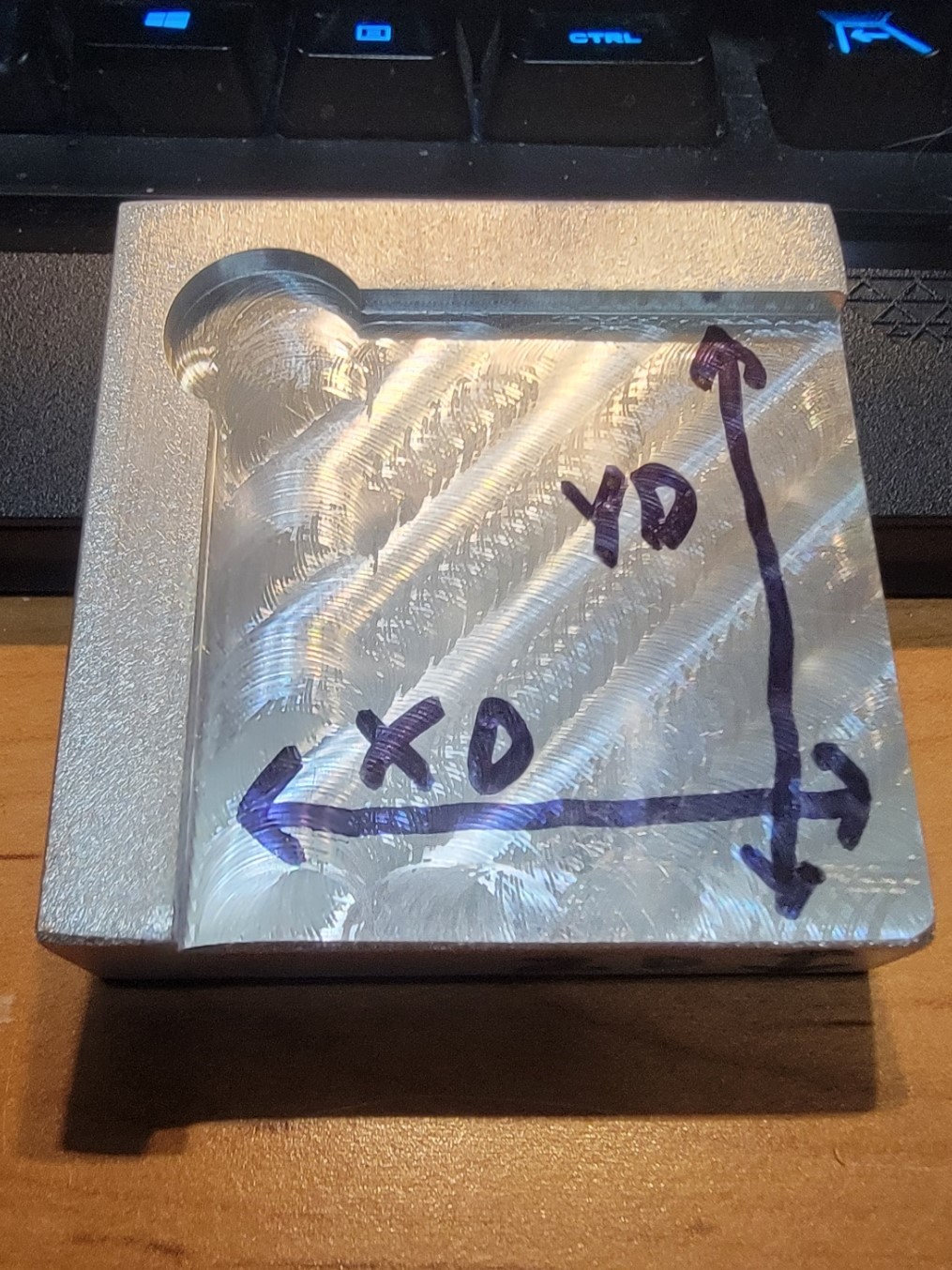
Next, referring to the two images below. For the X and Y measurements pay particular attention to the orientation of the touch plate in regards to where the half circle is milled out on the bottom. Measure along the outer edges of the touch plate indicated by the arrows and write down those measurements for XD and YD. Then looking at the touch plate from the side, measure ZD and write that down. You can also get these measurements under the settings tab in your controller but measuring them yourself is always best if you have a decent set of calipers.
XD=____________ YD=_____________ ZD=____________
BR = ________ RADIUS OF YOUR BIT. (1/2 THE DIAMETER)
(This will be the portion of the bit that will make contact with the X and Y axis when probing. This is usually the fattest part of your bit.)

- Now do the math filling in the blanks by calculating the equations to determine the values for X Y and Z
G92 X_._ _ _ _ =XD + BR example G92 X2.5032
G92 Y_._ _ _ _ =YD + BR
G92 Z_._ _ _ _ = ZD
-
You should now have the values filled in for G92 X G92 Y and G92 Z. Copy those values and replace the matching X Y and Z values preceded by the *****. Be sure to remove the ***** before saving the file.
-
Once the file is saved, send it to your controller just like you would any other carving file.
-
Jog your machine into position of zeroing. This will be different that the standard OneFinity way. You bit should be located about ¼ inch to the right of the touch plate NOT OVER THE TARGET CIRCLE. The tip should be below the top surface of the touch plate as low as you can get it and still prevent the collet from hitting the touch plate as the spindle moves around during probing. It should also be adjacent to the target circle. See the below image for the correct starting point with this file.

-
When your ready, just send the code to the machine just like any other carving file except don’t start the spindle!
-
When the process is almost finished y8ou will get a popup message telling you to remove the touch plate and magnet. When you click the OK button, the machine will move to X Y Z zero. The feed rate for this move is a little slow just for safety. You can speed it up when you are used to what is happening by editing the second and third lines from the end of the code increasing the F value which represents inches per minute.
G20
G92 X0
G92 Y0
G92 Z0
G38.2 X-1 F4
G91 G1 X0.125 F35
G38.2 X-1 F2****G92 X0.0000
G91 G1 X0.06 F40
G91 G1 Y1.00 F40
G91 G1 X-0.625 F40
G38.2 Y-1 F4
G91 G1 Y0.06 F35
G38.2 Y-1 F2*****G92 Y0.0000
G91 G1 Y0.125 F40
G91 G1 Z 1 F40
G91 G1 Y -0.625 F40
G38.2 Z-1.5 F4
G91 G1 Z0.1 F35
G38.2 Z-1 F2*****G92 Z 0.0000
G91 G1 Z0.125 F35
G91 G1 X1 Y1 F40
M0 (MSG, WARNING REMOVE YOUR TOUCH PLATE AND MAGNET THEN CLICK OK AND YOUR MACHINE WILL GO TO X Y Z ZERO)
G90 G1 X0 Y0 F20
G90 G1 Z0 F20
G91