I am getting tired of tabs, double-sided tape, and other tedious forms of workholding, so I’ve been thinking about converting my Woodworker QCW into a vacuum table. It’s shaping up to be quite an investment, so I figure I’d post my plans here first and open it up for others to critique, point out any potential shortcomings, help over-engineer, or just copy for themselves.
This plan will involve making 3 vacuum zones that can be turned on or off individually. The business end is currently a 3.5 CFM oil-free vacuum pump. I have no idea if this will be sufficient for CNC vacuum chucking, but it is similar to what AirWeights includes in their prefab 24x24" kit.
Please take a look and let me know where I can improve.
Sorry about the screenshot of links - could not figure out how to embed a table.
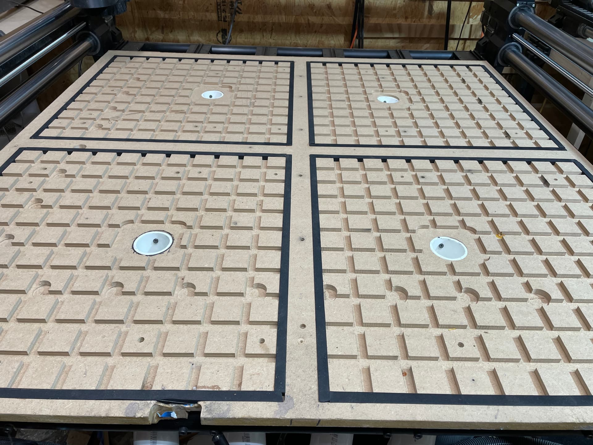
Here, each main panel of the QCW is a distinct vacuum zone, that can be turned on or off with a valve at the pump. This grid consists of 1/4" channels, which will be sealed with lacquer or another sealant. There will be square gasket cord that sits 1/16" proud of the channels to line the perimeters of each zone. The threaded vacuum harness is fed through the ports and held in place with gasket locknuts on either side - the harness will sit just below the underside of the QCW.
On top of the plenum, there will be a bleedboard - 1/2" MDF surfaced on both sides for permiability, then lined with tile gasket on top, and finally bolted into the QCW t track with countersunk hardware. The tile gasket is supposed to reduce leakage by focussing the vacuum to a grid of holes, provide a bit of cushion to compensate for an imperfect workpiece surface (i.e. act as another gasket), and finally provide some additional lateral friction for workholding. Seems to work well based on videos I’ve seen. The edges of the MDF will also be sealed with lacquer.
I like your overall design - seems well thought out to me. Considering doing something very similar to my machine. Plumbing will be slightly different as I plan to use ‘push-to-connect’ style. I’ve tested it and it’s good. Also very easy to reconfigure - no tools necessary to connect/disconnect. Looks like you picked out a nice pump! I going cheap for the pump during the onset of this experiment. I figure I can always sell it in lieu of a nicer one if I need to go that way. I heard about the oil filled pumps (like the one I ordered) getting hot and making a mess so the caution flag is up! Haha! Hopefully I won’t be running it long enough to get hot - so far, I’m just cutting out pickguards for guitars…
Not yet! I recently moved and found out that I need an electrician before getting back in the saddle. Other priorities have kept me busy. Let me know if you beat me to it - I’m happy to share vector files if they would help (haven’t made tool paths yet).
This is a really nice and well thought out design. If I can make one fundamental suggestion it’s to get a higher CFM pump. 3.5 will likely work OK for the area (24”x24”) shown, but if you can get to 5+ you’ll have more options open to you and less potential insanity chasing small leaks. If you miss any sealing surfaces with the lacquer (or other sealer), the plenum junctions, etc… you’ll have more flow rate to overcome small leaks and maintain a decent vacuum level.
One other thing to keep in mind are the gaps for your T-track in the QCW. It may be worth sealing off the opposing strips on the underside of the “bleedboard” with lacquer also, especially if you’re sticking with the 3.5 CFM pump.
You may also need a T-fitting in each airline in the diagram shown since you have 2 ports in each individual plenum. If you’re looking to save on fittings, plastic barbs also work well with the braided hose shown at a fraction of the cost.
Looks like you’re going to get a great result with careful attention to sealing. Nice work!
toiyabe_vacuum_qcw_files.ai (1.2 MB)
Here is the .ai vector file for anyone who wishes to play with this. It’s a bit rough, but hopefully the layer names are intuitive enough.
Note that the front left “port” is currently in a position that would not allow mounting of a controller or PSU box under the QCW. Either the ports or box will need to be flipped to the rear.
Thanks! I originally wanted the smaller pump for the lower amp draw, but it turns out that the vendor mentioned has a 5 CFM pump at nearly the same draw. Regardless, it looks like I am putting in a circuit or two in my new garage. Hopefully I can tackle this sometime this winter.
Full disclosure, I never ended up building this as I got sidetracked with too many other projects. I did however reach out to @AirWeights (@makerjace above), asking if he had considered doing something off-the-shelf for the QCW. He had some ideas of his own and we kept that conversation going. About a year later, he has a polished QCW vacuum table kit available through 1F and AirWeights websites. I’ve got some of his early prototype panels on my machine, and they are fantastic.
If you are intent on a DIY solution, I would recommend using HDPE instead of MDF and tapping the threads for plumbing (tapered taps available on the website in this post where I was sourcing the other hardware). HDPE will also save a lot of headaches when it comes to sealing leaks. I think I had originally envisioned using gasket nuts to secure the fittings to the table, but I don’t know how well that would work with tapered pipe threads. For actually drilling the holes (or pilot holes for tapping), I would probably just pocket all the way through the wasteboard with an end mill - just be careful if you have your PSU mounted directly underneath. I’m not sure if I understand your comment about needing a longer bit to accomplish this.
I also underestimated the pump size needed for this build. 9 CFM seems to be a sweet spot for a Woodworker size table and is what Jace includes in his kit (and sells as stand-alone).
Thanks for the info, what I meant about the drilling is to get to all the holes for vacuum fitting you would need a channel to connect them (assuming the bottom of the plenum you want to keep solid). I thought exactly of drilling thru the base board for the plumbing, but was trying to come up with another way in order to not puncture the base. I thought of routing a channel to connect all holes deep enough to accommodate the tubing to connect all pump connections. Just thinking out loud.
I have made a table using 2 1/2 inch vac holes thru the base table and plumbing that way. Use MDF but the HDPE sounds better, alot of sealing and such with the MDF.
@bgeorge Ok, I think I understand - I had originally planned on drilling clear through and connecting the port fittings with vacuum hose underneath the table. Another option would be to channel the reverse side and seal with some means of gasketted cover plate.
here is qcw vacuum table, i did real quick
2" pvc. installed slats, took measurements of locations, for holes and slats, put 4x4 piece on it and started cutting. cut holes in middle of slats. put 4 ball valves in(from lowes) and grabbed 6.5 hp hart brand shop vac from walmart(69 bucks).
made grid 3/8 x 3/8. found the vacuum grid foam on ebay for about 35 or 40 bucks. came with enough to maybe do 2 sets fo boards. can prob reuse this a couple of times. keeps air from sucking around edges which really affects performance. that said, i put gorilla tape around the edges to cut the 1st 400 sheets of ply. i cut a lot of cabinets and cut 1/4, 1/2, 5/8 and 3/4 hardwood plys, some boxstore cheap plys for my shop, and melamine in 3/4. cuts like gravy. i use 1/4 jenny bit and cut full depth on all the cuts. i also use nic frost cnc bits on his 1/4 mortising bit. works great. on melamine, it is so sharp it will cut your fingers just picking it up. no chips. fyi, i have to dump my jet 2hp dust collector (35 gal) 2 times a week right now.
I don’t think I would use any vacuum system. how do you use them without cutting into them or are they only for using without cutting out the item. I’d be afraid of ruining the thing accidentally going a bit too low.