My machine is a 1F Elite Masso Journeyman. I first saved my settings to a dedicated usb stick for my normal 3 axis setup before doing anything.
Then I did the setup changes on F1 Screen:
• Setup input 17 to be A-Home Sensor. Note the default was not inverted, so invert it as the other homing sensors are.
• Setup input 23 to be A-Axis Motor Alarm (note my input for this is 10, but works the same)
• Change Homing to include another sequence after Y, ticking the box for A. Note, I double up X & Y homing at same time, so mine was seq3. If separate, then it would be seq4.
Then on the F3 Probe section you will want to update the following values:
• Set X-Offset to -125
• Set Y-Offset to 55
• Set Z-Offset to 35
• Set upper right quadrant to 18/18 as the puck on the rotary for probing isn’t that large, so 18’s will not let it overshoot the y axis.
Now when probing, I probed Z first, then I probed x/y. This will give you the following results:
• Z will be on the centerline of the chuck top to bottom.
• Y will be on the centerline of the chuck front to back.
• X will be +20mm from front face of the chuck jaws. If using the alternate set of jaws instead of the mounting plate, this will give you 25mm of unused stock on the left of the carve.
On the A axis, mine is normally machine zero at -10.9 deg using a magnetic level to check (ie the square stock I have is rotated with the flat spot -10.9 deg toward front of machine). As this would leave the stock for setting up in carving later at an odd starting point, I rotated A to be a flat top, and set A Zero to that point.
I initially tried to use Fusion 360 to set up a model with a bottom jutting cylinder and top cone for clearance, setting up model to use the space from 25 mm from chuck end of the stock to 11 mm to tail stock, or 117mm of usable stock for a 153mm long 2 ¼” square.
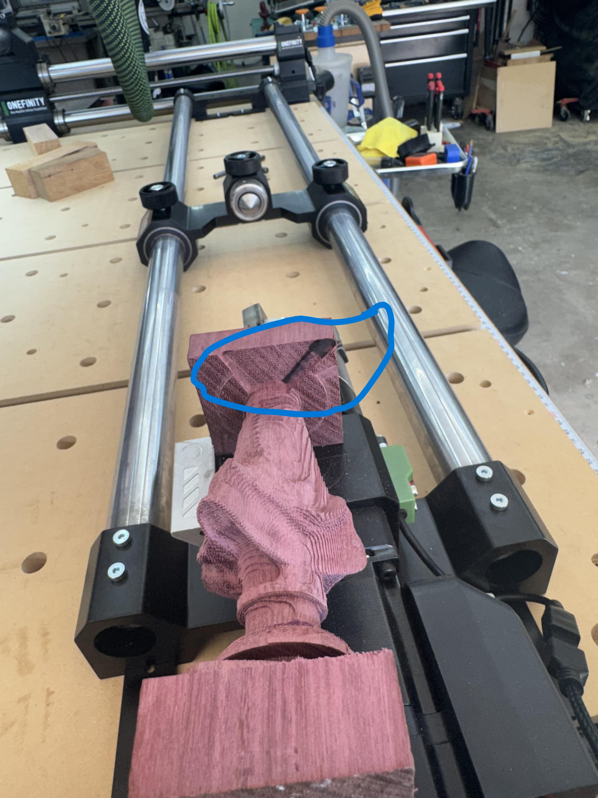
Now, fusion 360 has support for a fourth axis, but only if you pay ($$), as it will cost like 10 tokens/day at a cost of $30 for the 10 tokens, bit negative. Also, I had to pull an older postprocessor from blagistein?? that had 4th axis support to get it to work. I was able to use the 14-day trial to get a test, and glad I did, as I did have luck on a smaller test model of rounding the square, roughing it down with a ¼” bit, then using a 1/32” ball nose taper for finishing. It had some errors where the non-cut movements actually intersected prior done sections, but minorly. I then tried the scaled-up version for and that’s where things went wrong, as during the model roughing, it chewed through the model in several places during just movements, and also exceeded the tailstock boundary into the small section with a violent move into the remaining stock, violent enough that the A axis alarmed out, and the carve quit.
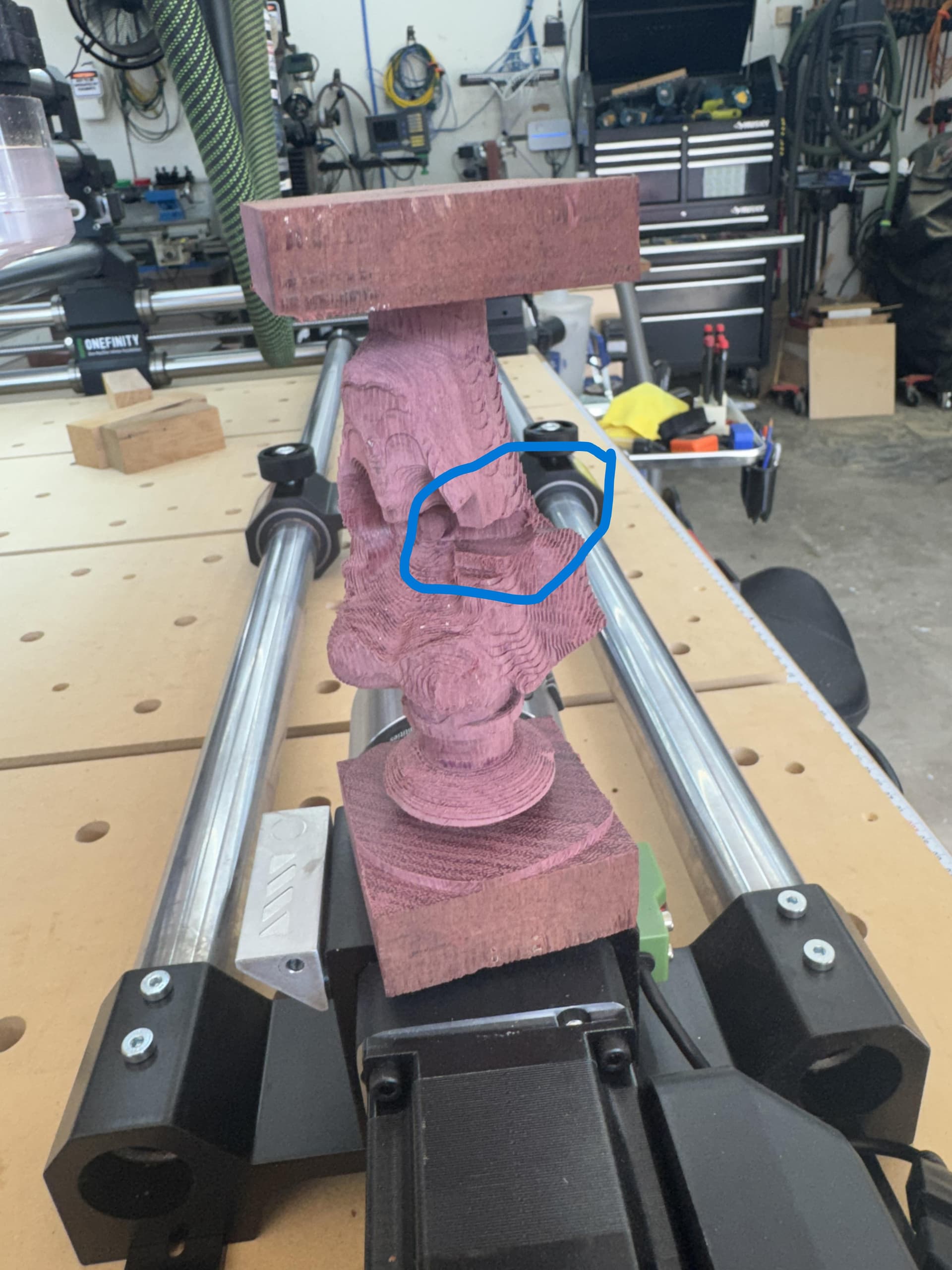
pics of mentioned scars from F360 output.
Side note on F360, it will spin the model on a axis like crazy, so I ended up in some cases with the A degrees into the 10’s of thousand degrees. I had to modify the Masso setup to exceed the max A rotation to allow this, an unnatural ungodly act.
I tried very hard to get it to work well in F360, but to be honest, the multi-axis extension is just not really a good fit for the masso/elite setup. It does offer some real 4th axis functionality, and worked wonders on simple operations, but for carving not so much.
At this point I started exploring other options, Vectric, Carveco, and was less than pleased with the Vectrix trial, as $700 for the proper version to do anything, and I was missing some tools I would really like in a software set for a CNC. (note I’m a long time f360 user, and will still continue to use it for 3 axis machining and also model setup for other programs) In addition, Vectric doesn’t really support importing 3d models other than stl’s.
Carveco I shot before I even got out the gate, as it really can’t do much more than column work, not a full bodied stl as a centerpiece, ie wanna do a chess set, forget it, and price again was high.
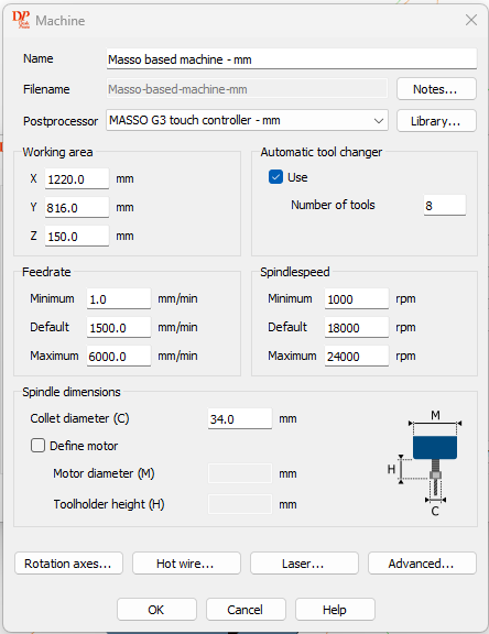
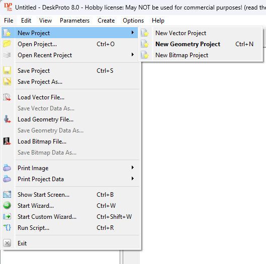
Lastly I tried DeskProto, and boy glad I did. For only $280 for a perpetual license, you get a well thought out 4th axis experience. It does have the setup for Masso G3 (inch or metric) post processor already built in. I did make some mods to it, as it needs to know more about the 1F setup. On the machine I tweaked the work area, federates, and spindle speeds to match my Journeyman/Spindle. On the Postprocessor, I tweaked the start/end gcode to be more like the official postprocessor output from f360, the spindle speed tab to give correct output (was only originally the S10000 command, not the S10000 M3 command), and the Tool Change tab to add a M9 prior and M8 after call to stop/start the coolant flood ie vacuum.
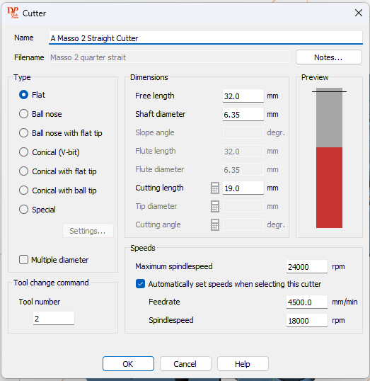
Some missing niceties, the tools are kind of barebones, ie there is no vacuum use callout, so thus I added it above around tool changes. It also is missing some data, and doesn’t grok like vbits as it requires the shank to be the same size as the major diameter of the tool, something that was a bit wonky, but really no effect on end product.
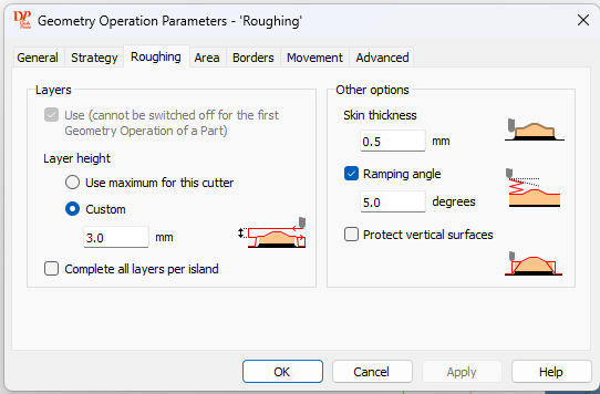
Now some of the nice, it actually understands square stock! This means I was able to rough directly from square stock down to the model, and only add a finishing pass with the tapered ball nose. In understanding square stock, it will only try to do the milling of the corners first, ie no wasted air carving of the flat faces. It will also maximize model to fill some of that dead corner space. In F360 roughing, I had to tell it how far to step down, ie copypasta several roughing passes to the model because it really didn’t have an effective roughing strategy down to the model rough surface, annoying but doable. In DeskProto, not an issue at all to call out step downs and leaving a skin, it’s callout for roughing above model height, to get the same easy 1 tool affect. I did verify the roughing pass in gcode was doing about .4-degree rotations, as it is by step over size, and not degrees as it was in F360.
Sidenote about inspecting gcode, make sure the first time and anything you change drastically to inspect it, ie your X should not be out of bounds of your workable area, A should stay within 720 degrees, and Z should always be working down from safe height and never really approaching zero (unless you expect it to…). I was able to see that you do get a nice masso preview of the X axis range at bottom, and it clearly shows that my bit would never go below +25 up to +114, my expected work range. It was only after checking my gcode that I caught some of the changes I made to machine/postprocessor/geometry operations that made me confident in the output solution.
Did a sample air carve, and then just ran the job. Success on first try! Deskproto’s gcode breakdown looks very similar in action to a 3d printer, ie if it has separated islands of same depth to do while the A axis rotates, it breaks it into smaller areas, doing each separately, until the two merge again for full length passes, it is very orderly, and the simulations are spot on to actual action. It neatly stayed in its expected work area, never wandering, and gave great results.


Also note the manual/help sections for each sub tab in DeskProto in the setup links to the manual section directly, and the manual does a very good job explaining each item on that subpage.
Last note about object references, I only used the stock probe plate as part of the revolution to get a xyz that sets the center of rotation on A axis, leaving from front face of probe area toward stock, x is 125mm out, y is over the center line also, and z is on centerline of rotation. I didn’t need to probe the stock at all. I like to think in terms of the centerline always, and set the origin of my stock to be the center of that cube. This makes it very repeatable no matter the stock dimensions. I also for my revolution, only change the A0 rotation to make sure the top of the stock was flat to the table using one of them magnetic angle finders. Just measure table on front to back axis, then on top of stock. Mine was built with the chuck Machine A0 actually being -10.9 deg from a flat top. I did notice that once you have probed the revolution, it always is known to the machine for reference x/y/z/a, and so I only had to probe it once no matter how many operations/models I did. Probably only have to do it after machine change over to add revolution back into action.