Okeydokey, here is what I setup to work for me in DeskProto V8, note if and when you choose your version, make sure you get the multi-axis addition, I also chose the hobbyist license, which is 248 Euro, or the $ equivalent for exchange that day.

test merge.stl (19.8 MB)
I included the model for test purposes, and you can see in the picture I have it orientated along x axis with origin at the bottom middle.
Next up is the Machine Lib. Note I’ll only show the tabs I changed over the default selection. Under Options→Library of Machines you should see this:

It should have your original choice of machine highlighted, I chose the metric version. Just choose Edit. Next up, the main page:
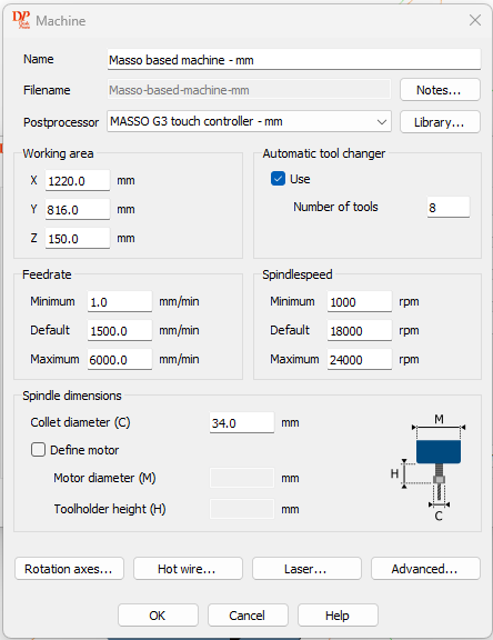
I updated my working area items from defaults, and possibly feedrates. I definitly change spindlespeed and also updated collet to match the ones for my spindle.

Lastly on advanced item, I only updated the correction factor. This gave me over 4 hours 1 min difference between the calculated times and actual.
On to the PostProcesser changes, again choose Option→Library of Postprocessers, you’ll see same as before:

name should be identical to Machine library choice, choose Edit…

I again am only doing tabs I changed, in this case Start/End. Note the spaces at the front of each line. Top of Start Command up to solo G90 pretty stock, M5 is explicit command to turn off laser. End command starts with M9 to turn off vacuum, innocuous to leave in, after that pretty stock moving Z up, A to zero, but I chose to move my spindle back and away from my rotary setup, you can choose differently. Last command does a program stop and rewind. Make sure to add %, as that line won’t get a line#, but if you don’t add it, M30 won’t get a line# as a result.

The Spindlespeed one didn’t have an end command, ie include the M3, so i added it in. This lets the masso controller take over the spindle startup sequence.

Last Postprocessor tab to address is Tool Change. You don’t have to change it if you won’t be running the vacuum at all, but if you do, it first turns off the vacuum, does tool change (manually or ATC), then adds back in vacuum start.
I’ll also add in my part setup, here is my proj list:

small and to the point, first “Geometry operation” i renamed from that generic to Roughing, could have done the same with last which is finishing. Clicking on Roughing, I set it up like so:

I set this up to use my Masso ATC cutters in the Library of Cutters, choosing a straight cutter adn feedrate and spindlespeed. Note, I chose too fine of a distance between paths, it could have been rougher than that, say 1.5mm.
Strategy tab:

I chose the simple parallel along X axis. The Main looks interesting choices, but I’d keep the details the same. The manual does a excellent job of explaining the choices, simple hit the help button. Next up Roughing tab:
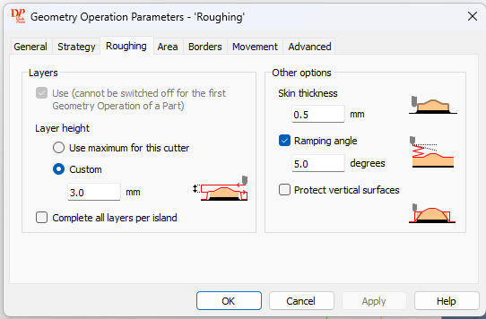
Under Layers, sub section, I chose custom 3mm. This sets the depth of cut for each roughing pass down to the remaining skin depth you choose. .5 or 1mm should do fine to leave most of the finishing done by the ball nose bit. I didn’t originally chose the ramping angle, but noticed that it will just plunge down your depth of cut to just start the pass, so I’ll be doing future with the ram set.
On the finishing step, general tab, updating cutter, precision, feedrate & spindlespeed. The


On Strategy, I again chose same as roughing, parallel along x axis. On Roughing, it was no layers use, and zero skin thickness.
Just to quickly cover a cutter setup here is for my 1/4” downcut bit:
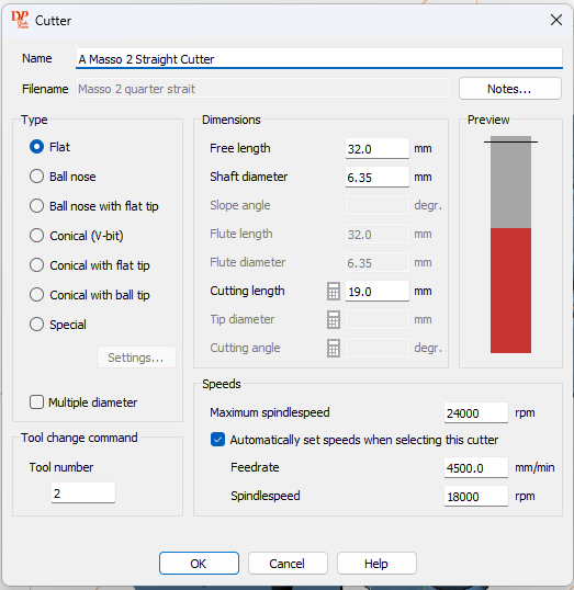
Important things to know for ATC is tool number, probably free length (the length extended beyond the spindle nut, and cutting length.
Lastly, I didn’t cover this first, to start a new project similar to mine, you would choose as below:
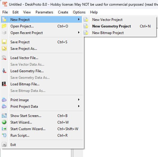
After that you can double click the Part to get the Part Paramaters, it is the second item in this list:
You’ll see this screen with tabs:

make sure to check use rotation axis, as this tells the software your going to do a rotary.
On the transform tab:

you can play with the rotation to get your mid axis to be down the center of your part, make sure center geometry is checked.
The material tab has this stuff:

with the important part being the shape. I chose Rectangular centered, but if you have a cylinder or possibly eccentric, you can take advantage of that.
I don’t think I changed the zero point tab, but here is what it is:

lastly, an alternate way to get to part parameters is this (right click for pop down menu):

This is where you can add more geometry operations, ie more toolpaths.
Note this software I only covered as to 4th axis, it is actually a fully formed 3 axis tool also, but I like to do my design work in 360, but it looks like you could for a cheaper set price make this work all the way around. As for BB installs, I think this would work better than just fine also. Check out the vector ops in particular, seems to be deep in that regard also for vcarving or just plain dxf cutouts. Do note on the part parameters page, it’s a simple uncheck box for use rotation axis, so the multi-axis software supports both 4/3 axis normally.
If you are looking for a good alternative software for either rotary or just 3 axis, this for my first cut is just good. Note I only found out about it yesterday afternoon, purchased it from the developer just last night after more research, and installed, configure, and ran my first project this morning, it is stunningly good for affordable software that is a decade old! the website is not up to date, but V8 is out within the last year, and documentation and tutorials have also been updated.
Cheers,
Dave