A bad letter H, considering GCode and Backlash

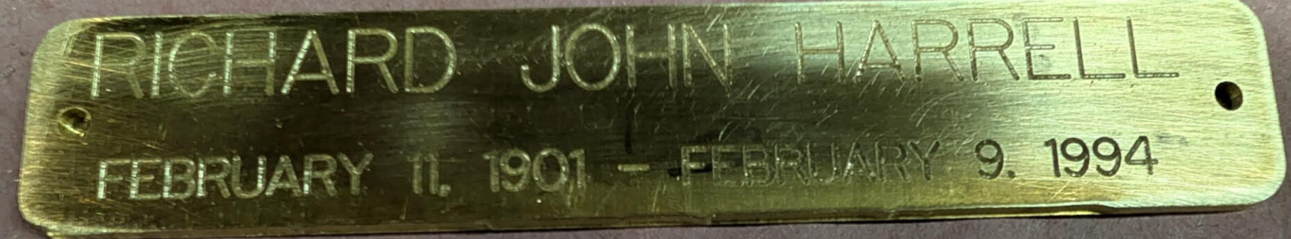
I am trying to engrave names into C260 brass, and I don’t like the results… specifically the letter “H”.

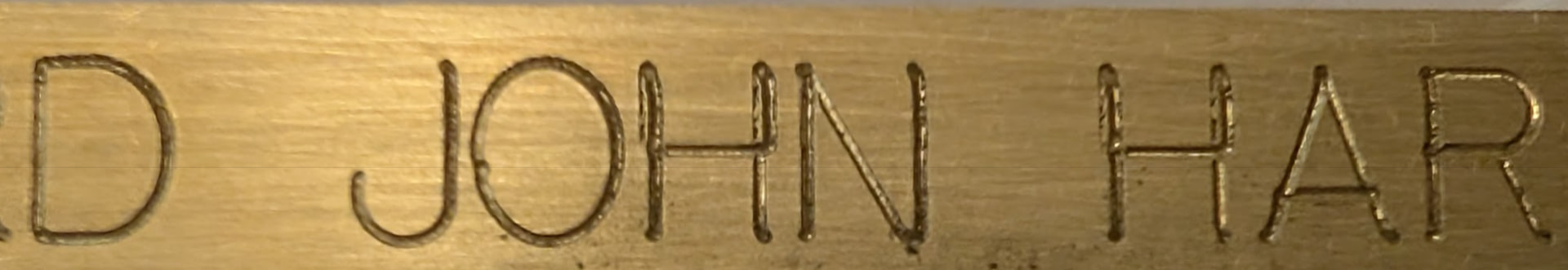
The failure seems consistent between two instances of the H and in fact is the same over three.

The Gcode for this came out of Vcarve Pro 11.5. Quick Engrave, outline, 16000 RPM, 40 inch/min feed, 15 in plunge. 0.01 depth of cut. The bit being used is a Lakeshore Carbide 0.020 dia 20 deg engraver. (looking at the pic the error seems to be a tool diameter or 0.02 inches)

I run this path twice to get a final depth 0f 0.02 in. Things actually look pretty repeatable considering the path is run twice cutting 0.01 in each time.

Frankly the Gcode looks reasonable:

N27 G00 X0.0135 Y0.1000 Z0.2000

N28 G1 X0.0135 Y0.1000 Z-0.0100 F15.0

N29 G1 X0.0135 Y0.3800 Z-0.0100 F40.0

N30 G1 X0.0135 Y0.2456 Z-0.0100

N31 G1 X-0.1735 Y0.2456 Z-0.0100

N32 G1 X-0.1735 Y0.3800 Z-0.0100

N33 G1 X-0.1735 Y0.1000 Z-0.0100

N34 G00 X-0.1735 Y0.1000 Z0.2000

You can see the letter H does double back on itself to create the “cross member” but the X value stays the same. With that I believe the Gcode is fairly sound.

So I am now looking at the machine and work holding.

If it were work holding, wouldn’t you expect to see other letters affected​? There are only 5 letters shown but out of 18 letters only the Hs appear misshapen. So I am thinking the work holding is reasonable.

Going back to the machine it is an Elite Foreman with the stiffy option. I spinning a 3HP spindle with ISO 30 tool holder. Again, at least to me this all seems reasonable.

I did consider backlash as a possible cause, and even tried to measure it. Looking at the Gcode X should not be trying to change, but you can see that it does as it back tracks.

The Masso controller supports backlash correction, but I believe that is for when the screws change rotation direction. As the axis is not moving controller backlash support should not come into play.

Now to get into what I think is happening ….

I don’t believe that rules out backlash though. Consider this picture.

Backlash would be the “white” distance between the two threads. Could the cutting force of the bit as it changes direction move the X from a leading to a lagging loading point.

If this is the case then any reversing and re-cutting a tool path is likely see this artifact, as you toggle between leading and lagging contact points.

But then this doesn’t make sense considering backlash on the onefinity seems to run at 0.005 inches …. does the machine stiffness make up the other 0.015 inches?

As you can tell my brain is starting to hurt…. Does anyone have any wisdom to share?

1 Like

What program did you use to create the letters?
It is possible to have letters stacked in layers.
But I do notice there is a slight jog in the top part of the letters

1 Like

VCarve 11.5 stroke text …. I have included the GCode that VCarve produced. The GCode seems fine.

Certainly I could edit the GCode so that the drawing of the H was always done in single strokes, with no re-tracing but that is extremely tedious.

1 Like

Maybe check the ballscrew to stepper coupler to see if its tight

1 Like

Things seem tight. Doing the https://www.sherline.com/wp-content/uploads/2020/07/masso_adjust_backlash_inst.pdf tests all seemed reasonable.

Tomorrow I may run a test with “hand written GCode” that just engraves a vertical line, then returns along the same path. I will start with the same parameters feeds & speeds and DOC.

Then I will drop the DOC to see if reducing the cutting forces shrinks the “kick back”. Remember we are toggling between conventional and climb cutting.

Again I am just brain storming.

1 Like

To eliminate the software, on a scrap piece engrave 3 different fonts that are similar to the original like Arial for instance. If the error still occurs, then it’s not a software issue

1 Like

Where did you get this backlash number? I dont have any backlash compensation setup and now I am wondering if I should.

The shape of the machining path appears to be consistent with about 0.01” of bit deflection. If I found the right bit, and did the math correctly, you have a chip load of 0.00125”. I have no experience machining brass on a Onefinity, but that seems fairly high for a bit with a tip radius of only 0.010”. You might try cutting the feed rate in half, and see if that gives better results.

3 Likes

Backlash could be it, but I think it’s much more likely something is loose or worn on the machine. The red coupler in the motors for instance could be worn, and your results would be consistent with that condition as well. Any loose bolts, loose motor, loose bearing block, could do it!

You could help diagnose by running the text vertically instead of horizontally. Depending on how the error looks after rotating 90°, would help determine loose components vs deflection.

1 Like

BuckeyeDennis… VCarve is saying a chip load of 0.0013. I can certainly drop that by dropping the feed rate from 40 ipm. Where Chip load= Feed Rate/ (RPM * Number of flutes)

You say 0.0013 seems high what would you expect to see? And is this number gained from experience or an engineering model?

Silly me went to CoPilot AI for recommendations and it suggested between 0.0015 and 0.003, so seemed reasonable to me, especially with the comment “These values assume slotting or light profiling.”

Based on your comment I told the AI the bit was 0.02” dia. That hanged the response dramatically.

The new response was:

With a 0.02" diameter bit (about 0.5mm), you’re in micro-machining territory, and chip load must be reduced significantly to avoid tool breakage. For C260 brass, a reasonable chip load would be:

:gear: Recommended Chip Load for 0.02" Bit in Brass

  • Range: 0.0002" to 0.0005" per tooth

  • Ideal starting point: 0.0003" per tooth

This ensures the tool cuts cleanly without rubbing or excessive deflection.

So yeah a REAL heavy chipload.

Based on my 16000 RPM my new feed rate is 9.6 IPM, they also suggest a DOC of 0.005 to 0.01 …. so my 0.01 DOC is even on the high side.

1 Like

I’ve done lots of brass for copy fonts for a New Hermes engraver. Use a 60 degree engraving bit, single edge, run at 10000 rpm, 20ipm, 5 ipm plunge. d.o.c. .020.

1 Like

All of the points made already are very possible and the last one on using a 60 degree tool may be the best answer in my opinion.

I have another thought about deflection. If you have your “Z” mounted on the lowest point on the gantry could be the cause of the deflection. If you can raise it up higher maybe in the middle or the top of the mounting position could help the deflection because you would make the stiffy bar be closer to your working point. Brass is not very forgiving like wood is, so the closer you can work to the gantry bars the less deflection you will get.

As a machinist when working with 360 brass the more rigid you can make your set up the better it will machine. So if you are extending your spindle further away from the gantry the more chances it will deflect. Just my thoughts on machining brass in this type of machine.

I don’t have a lot of time working with this machine yet so my opinions are just me analyzing what you have said and what others have said to help change the results.

One thing you will need to learn is how to analyze the problems that will come up as you work with this machine.

I can tell already it won’t do what the industrial machines will do that I am familiar to using.

1 Like

Derf, I had considered the 60 V bits, but I was worried about the width of the cut… I have very little distance to work in X and Y. The bit I am using is one John Saunders (SMW) recommended years ago. ( Engraving Tools: Speeds, Feeds, and Tips! | WW237) John is no machining god but he seems to give reasonable advice.

I will try today dropping IPM to 6, 16000 RPM and .005 DOC and see how she runs.

Joejk, I understand your concerns about deflection. When I put my machine together I tried to minimize it … stiffy option but more importantly the spindle is a CNCDepot with an ISO-30 tool holder. The ISO-30 is no Cat-40, but it is a fair bit better than a Makita collet. No disrespect meant to the router folks, I ran one for over a year and for wood it was fine. The spindle is mounted to the Z Gantry via a custom Alum plate.

I am grateful to the machinists here, they have the gut feel I lack. I am a retired Mech E. who went back to community college and took cnc machining classes… yes the Haas machines would snicker at this problem. I think my machine is quite capable of doing this job. I am the weakest link.

3 Likes

Well once again I am the weakest link. Thank to all the folks who suggested feeds/speed/doc.

What I just ran was 6 IPM, 16000 RPM and 0.005 DOC. I ran the toolpath twice, dropping G54 0.005” after the first run…. so you get to see a bit of repeatability.

Here are the results:

and

So I am quite pleased with the results. The surface finish stinks as I just knocked off the burrs with 220 sandpaper.

This is C260 brass because this is for our church columbarium.. which already had C260. I am not a metallurgist and did not want C360 aging differently.

For me I believe this issue is closed, with me just going off to improve the cycle times. The machine sounded like it was coasting downhill, not working at all. I will first increase my DOC to 0.01” and then slowly increase the feed rate. ( I want a final DOC 0f 0.02” )

I was concerned about heat but it never got more than warm to the touch.

If folks are interested I will post the setup I am using … as in jigs and work holding.

Some day I might be able to call myself a rookie machinist.

5 Likes

Yes, if possible then please do post information about the setup etc. I haven’t done any metal engraving so far but have been thinking about it. If you can also post your choice of bits and anything else that comes to your mind. Thanks a lot!

1 Like