On the Elite Power Supply, is the Vacuum outlet connected to a mechanical relay or to a SS relay?
I have a vacuum motor that is 1 HP, 7.4 A FLC. The current rating is within specification (12A, w/ 10A fuse?) but I am unsure whether it can handle the inductive load of 1 HP. There is no HP rating for the relay.
I don’t have an official answer for you, but the receptacle on the US power supply is NEMA 5-15R, which means 120V @ 15A, but the fuse is only rated at 10A (Elite Masso Power Supply Fuse Schematics FAQ) as you indicated. I’ve seen this a lot where the receptacles are only rated for 10A even though they use a 15A standard. In fact it’s actually quite difficult to find a reasonably priced receptacle that is actually rated at 15A and even more difficult to find one at 20A.
Based on a different thread, it looks like the vacuum is solid state with an MOV across the supply line. I can’t see the part number for the FET (or TRIAC) but I’m guessing it’s not rated for 20A based on the size and the lack of a heat sink other than the copper on the PCB and the via stitching.
If you are adventurous, given the power supply has a fuse, you could try it out and if you fry the fuse simply replace it?
Thanks for the response. I appreciate the link for the picture of the inside of the power supply. However, it does look like OF is using a electro-mechanical relay for the Vacuum. Also appears there is a MOV and a RC network for contact arc suppression. My next question is, are the relays pluggable and what manufacturer and part number of the relay so I can do more research on this component. I do not have my Elite system yet. A few more weeks yet.
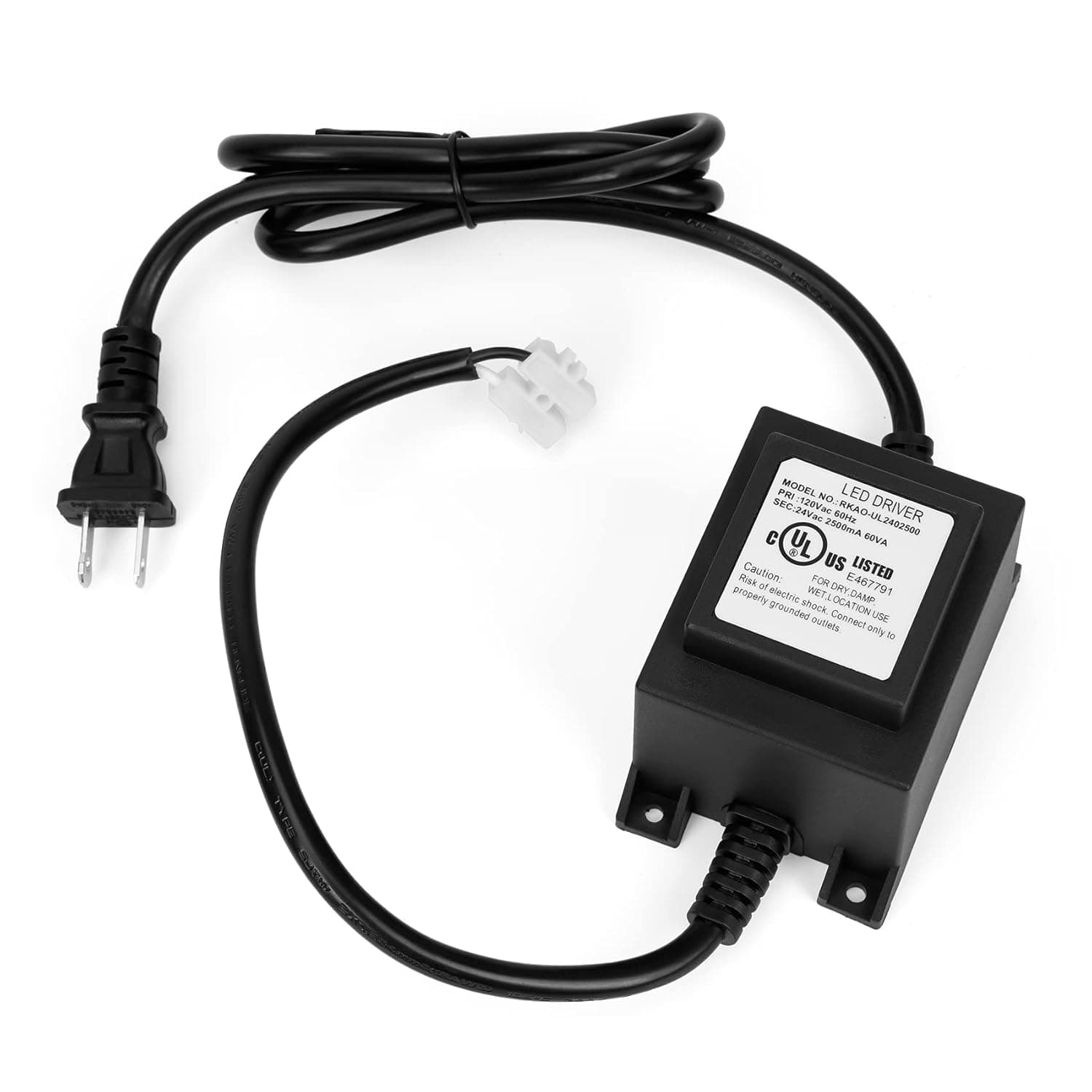
I decided not to take the chance with this relay. So I will install a small enclosed 24 vac transformer under the bench that plugs into the Elite power supply vacuum outlet. The 24 vac will then operate a small (24 vac coil) contactor HP rated for my dust collector. I used 24 VAC to avoid having two separate 120 vac sources in the same enclosure.
Personally I was not concerned about the motor running current. I was concerned about the relay itself failing when operating an inductive motor load and the high inrush starting current. Contacts on this type of relay may end up failing. The relay appears to be soldered in making it more difficult to repair.
I have done my set-up with the above enclosed transformer to be plugged into the Elite power supply outlet normally used for a shop vacuum. The transformer 24 vac output controls a horsepower rated motor contactor in a small enclosure. The contactor then powers the dust collector from its own separate 120 vac circuit.
Although I am waiting for my Elite upgrade to come shortly. I have wired it all up and tested it out. Should work fine for me. The small transformer is mounted underneath the bench nearby the Elite power supply. A low voltage cable from the transformer then runs over to the contactor enclosure mounted on the wall with the separate 120 vac circuit powering the dust collector. I also added a manual override switch so I can operated the dust collector separately from the Masso controlling it if needed.
I will include pictures later when The Elite upgrade is installed.
Yeah this is the way i will have to do it at some point. Except in my case I’m planning on wiring my DC as 240v/5.7A instead of the stock 120v/11A to drop the amp load. That inrush being my concern also as the 11A is is running draw, not startup.
So I just need an appropriate contactor.
I’ll be passing attention to this thread in the following weeks, I should have the machine soon enough
The contactor above should handle either 120/240 vac. It had a current rating of 30 A and 180 A starting current. It’s a popular low cost contactor often used as a replacement for AC compressor motor circuits. I ordered from Amazon.
This is how I did my power distribution for my Elite Woodworker. I ran three separate 120 vac circuits from the main load centre to there own duplex receptacles, one each for Elite, Spindle and Dust Collector.
@Phoenix have you got your machine up and running with this electrical setup? I am looking to do the same thing for dust collection automation. Can you tell me, how does the manual switch work? Is it getting its own power and supplying the outlet for the collector? And the contractor is also connected to the same outlet for the dust collector?
I have been operating this for awhile now. It works very well for me. I would not change anything. It’s completely automatic. Dust collector comes on right after the spindle comes up to speed and shuts down before a tool change and then starts up itself for the next tool path. You can also manually operate from the Masso itself.
It’s a single 120 vac source. I have a dedicated line from the breaker panel to a wall switch which then feeds a duplex outlet right beside it. The dust collector then plugs into the duplex outlet. The contactor is simply connected in parallel with the wall switch (two wires back to the wall switch). The contactor coil is a low voltage 24 vac which is wired back to the 24 vac transformer mounted under the CNC bench. The self contained transformer as depicted above plugs into the router socket of the Elite power supply.
I went with this method so as avoid multiple 120vac sources for the dust collector and to avoid running another 120 vac line from CNC bench to the Dust collector/wall.
I hope this explains clearly how I did it. If not ask away.
@Phoenix thanks! That does help me understand. Im thinking of expanding on this just slightly. If I use a 3 position switch, shouldn’t I be able to have manual on / off / auto (masso controlled.)?
I thought of that also, but for me could not see any extra functionality it would give me. The Manual wall switch gives me Manual ON/OFF if the Masso is powered on or off. If it is on the the Masso is another alternative for Manual OFF/ON. The Manual wall switch can even override the Masso Auto control if needed to be. It maybe advantageous if the Duct Collector is not close to the CNC. For me the Wall switch and Dust Collector are beside my CNC.
I would give some thought on how you define the function of the OFF position. Is it OFF for just Manual or OFF for both Auto and Manual? Good luck on your setup. Let us know how it works out.
@Phoenix Ok, Now that I’m getting into the weeds with this, I understand better. a regular interrupter switch in parallel makes more sense. The parallel part initially eluded my understanding. Here is a diagram of what I plan, exactly like yours I believe, minus the 24v step down. Right?
lol not as confused as I am by your diagram. obviously you are the pro electrician here! Thanks for making the diagram and hope it helps everyone else trying to solve this problem.
Basically I took the incoming power, black wire to both the switch and the contactor, then switch to outlet, and contactor to outlet. White wire goes straight to outlet. So switch and contactor can both power the outlet. 120v from elite triggers the 120v contactor. That makes sense in my head, but I have a loose grasp on what I’m doing. But no magic smoke, and my outlet tester says it’s wired right.


