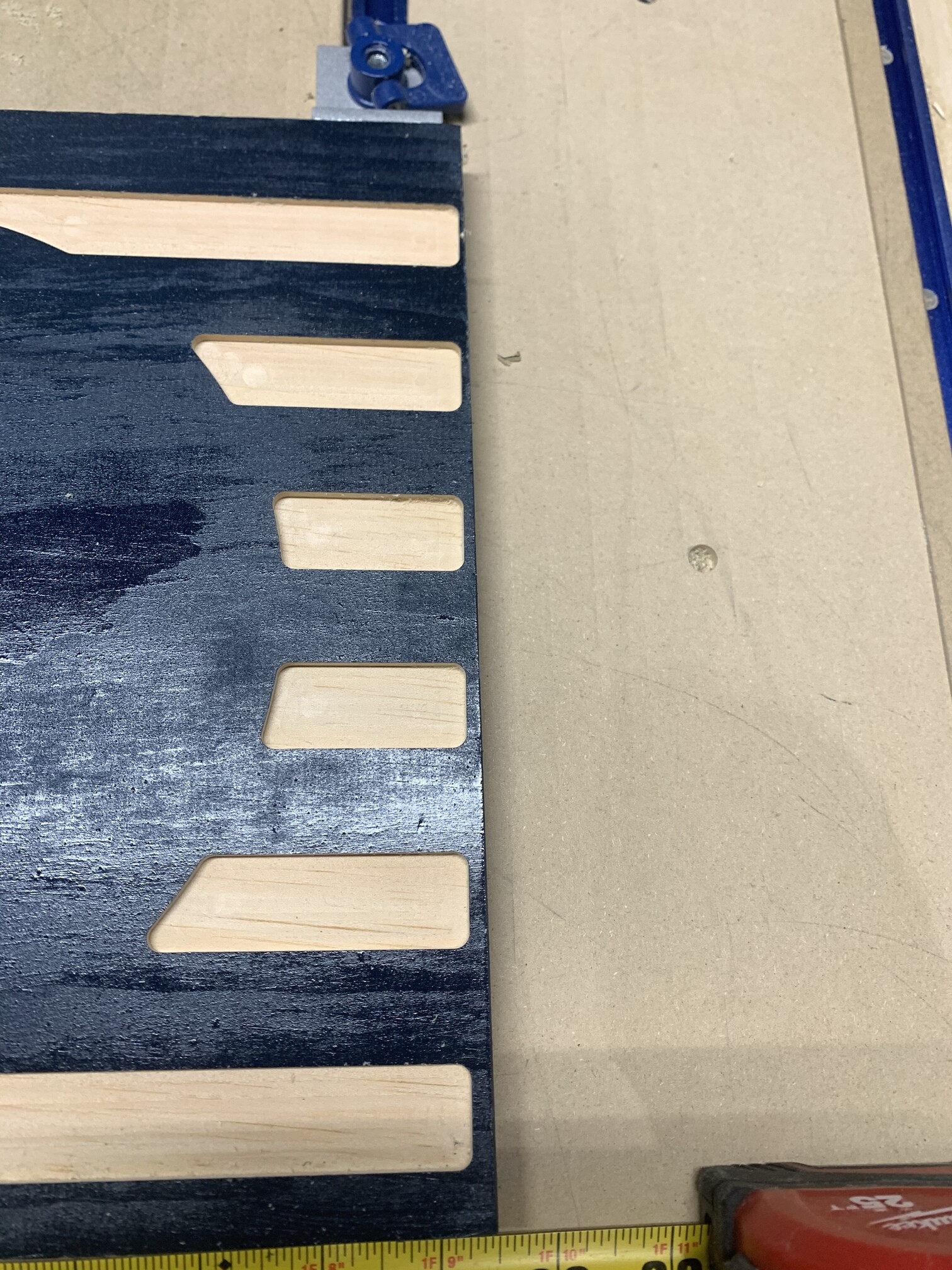
I’m attempting to carve out a USA/Navy flag; however, my alignment is off. As you can see in the pictures the stripes on my stock (11.5” x 21.5” x .75”) are coming out crooked. I designed the flag in Carbide Create and the lines are supposed to be .25” from the end of the piece on both sides. Before starting the project I used the touch prob to zero x,y, & z for a .25” down cut end mill. This is my second attempt and both projects came out crooked. I attempted the 2nd time because I thought my touch probe may have moved the first try. I watched closely on the second attempt when I zeroed x,y, & z on the probe. The probe didn’t move. Also, prior to saving the G code I changed the post processor to the recommend settings. I’m also running the newest version 1.0.6 with the recommended settings.
Why are my projects coming out crooked? Please help!
Kyle, I would first look at the machine to make sure your Y axis is running parallel to your T-slots. Then I’d recheck homing to make sure it’s fully homed on both Y axis sides, and make sure both Y axis assemblies are aligned in the front… making sure that one Y axis isn’t misaligned to the other one. This condition could cause what you’re seeing here.
Edit: In looking again at your project, it appears more like the wood piece wasn’t clamped square to the machine because it’s off in both X & Y directions.
another option would be to start with a full piece slightly oversized and let the CNC cut it out…that eliminates any issue with non square (relative to axis) hold downs, fences, etc.
I believe my issue may have been that my stock wasn’t totally square.
I was under the impression that when I used the touch probe for x,y, & z the machine corrected itself for any operator error of setting up my stock crooked when clamping it down.
I also thought I could, if I wanted to, cut a piece on any angle and didn’t have to worry about alignment as long as I used the touch probe.
I’m pretty green at CNC and I’ve learned a lot already. Sounds like I’ll have to cut some lines in my spoilboard to help with my alignment issue.
Thanks for the help!
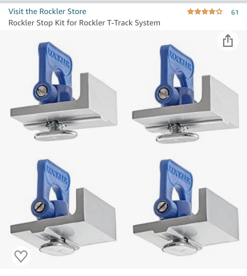
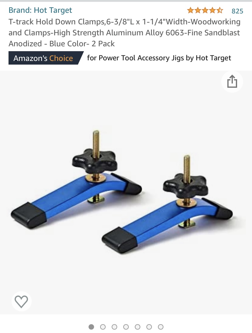
@Hnatman What kind of hold downs are those?

An alternative for you might be to use the bit as a locator for the Y axis at both left & right corners of the work piece’s front edge before it is clamped in place. I use the Y axis digital location to accurately guarantee measured material is aligned. It takes a little practice and patience, especially learning to pin one side while moving the other.
Of course, as was mentioned, the easiest way is to let the machine cut the outer profile with oversized stock.
One suggestion is to lay out a grid on your waste board. This will give you some visual reference points to align your project to making it quick and simple. Using the machine to draw these out will ensure that your projects are square to the machine.
Thanks for the tip! That’s my plan this evening.
Thanks for the information Kyle 
So I made a grid pattern exactly 2 inches square by 32” x 32”. I ran the CNC using a 1/16” end mill. Everything appeared to run fine.
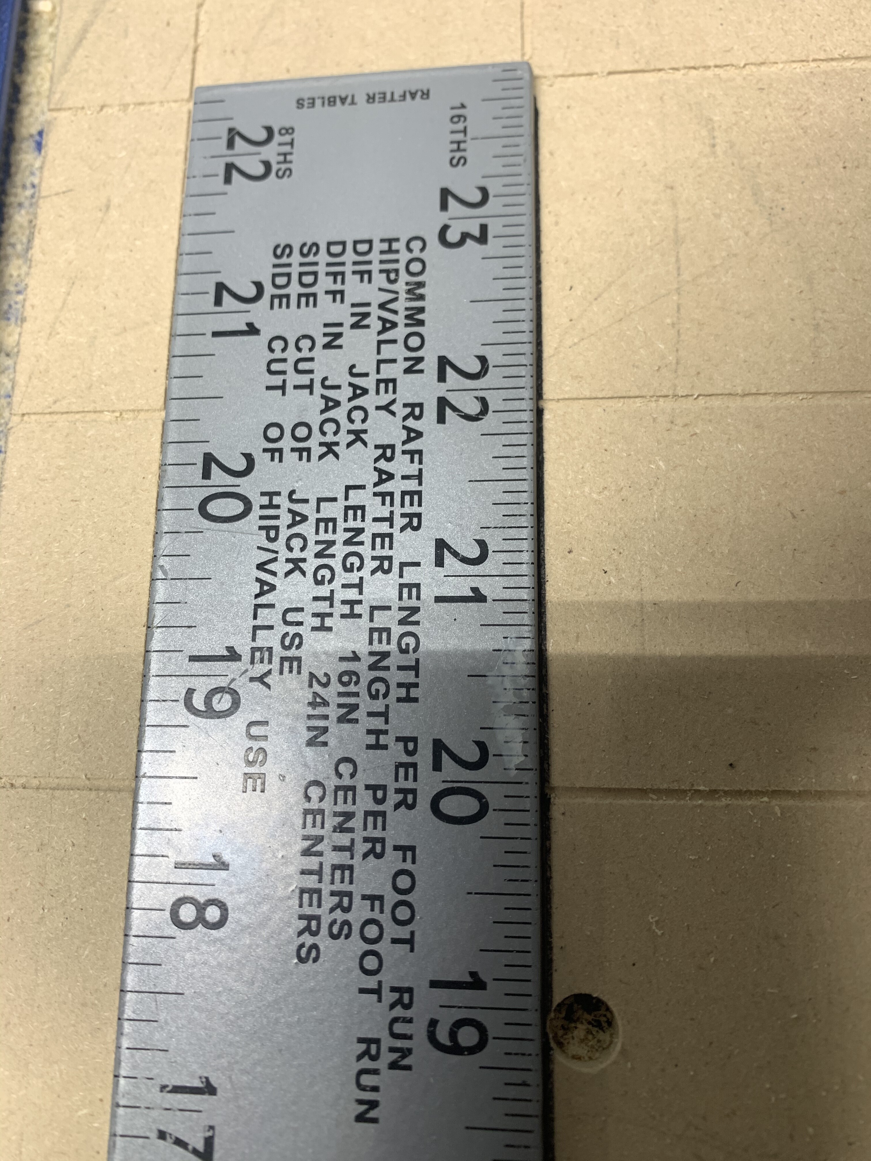
I put a square on the table and the grid isn’t perfectly square. I measured the y axis rails and they are exactly the same distance apart from front to back and side to side. I attached two pics of the square on the table and attempted to highlight the grid with marker. As the square goes back toward the back of the machine the y grid line starts to get covered by the square. If I square up on the y grid line the x gets covered by the square to the left of the machine.
I attempted the flag again and the project came out a lot better, but the stripes are still off 1/8” from the right side.
Any ideas what I’m doing wrong?
1st pic shows close up of square. 2nd pic shows square off on y grid.

Check to see if there is an error in the file’s code by running it again without a bit in the router. As it cuts on the Y axis the X axis position indication on the controller should show no change.
I’ll give this a try tomorrow!
Have you checked your square as well? Use it to draw a square or a t by flipping it. Check with inside and outside edges. You can usd a punch to adjust it.
I did check the alignment, but didn’t try drawing a square. I will also try this tomorrow. Thanks!