Brilliant! Thanks for posting this, I used this today on an epoxy inlay project in progress. I leave the piece mounted, but can now turn off my OF and get back to my XY origin between pours.
How is this simple instruction NOT in a 1F beginners guide? There are so many job situations where returning to the same position would be required. Many are asking in vague ways about it, and many are giving bad answers that only confuse the issue.
+1 for G28. I’d like to set “home” to the corner of my waste board rather than true home.
-Tom
I’m having a devil of a time tiling. I noticed when cutting 96mm dog holes (these are my reference points) in my spoilboard that the 1F likes being just a tad off from session to session, and so would love to know your homing switch solution with your 1F.
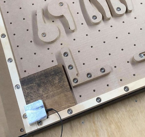
I had 3D printed mounts for NC proximity sensors on both Y axis rails and the Z axis rail and the Z axis and used sensors similar to this one (the specific ones I ordered no longer appear to be listed):
The main challenge was the sensors needed 12v or more to operate correctly and the Onefinity controller works with 3.3v logic levels so I used optocouplers between the 2. I have since moved to a Masso controller which works natively at 12v (or more) and has integrated optocouplers for isolation which simplified the setup. I’ll see if I can dig up some pics of the mounts but I don’t think I have anything saved on the 1F controller configuration.
The proximity sensor setup was well worth the time and effort to implement, I am able to power off the machine, power on, re home and pick up where I left off on a project.
Moved to a Masso controller? NC proximity sensor and mounts? Unless/until the upgrade path is available from 1F, I am extremely interested in any solution to the lack of session repeatability from my 1F J-man.
If I weren’t already bald, I’d be pulling my hair out in frustration with the open-loop stepper motors and stall homing on my 1F.
If you would expand on your solution, I would be grateful.
1F non-Masso controllers use Buildbotics, which is based on LinuxCNC.
I cannot find G02 documentation anywhere on that website, and don’t know if the interpreter would equate that with G2 (which has completely different functionality).
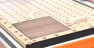
I’m wondering if I can manipulate my J-man’s workable area via G28.1. To be more specific, I’m contemplating a doghole-with-metal-dog-combination centered at (96, 96) to tell my machine where its workable area is via the G28.1 MDI command.
Hey Festdewalkita,
Buildbotics is not based on LinuxCNC, as Buildbotics is the own work of its creator, but its g-code syntax is patterned after the LinuxCNC g-code syntax
G2 (Clockwise Arc Move) is identical to G02, just as M3 is identical to M03.
The numbered parameters #5161 – #5169 store the machine coordinates of the home position for the axes X, Y, Z, A, B, C, U, V & W, therefore after homing, G28 moves to machine origin (aka ‘home’)
G28.1 sets these parameters to the values of the current position, but the position is in absolute machine coordinates.
You can check the values at any time with the g-code command:
M0 (debug, G28 settings: X=#5161, Y=#5162, Z=#5163)
I don’t know if you rather are interested in the G52 and G92 commands. After probing your workpiece in XYZ, the G92 command sets the new workpiece zero as the X,Y,Z zero position of the workpiece coordinate system. Any subsequent G0, G1, G2 and G3 motion commands will then take the workpiece zero as coordinate system zero. E.g. G0 X0 Y0 Z0 will then move to the workpiece zero. You can still move to machine zero (‘home’) with G53 G0 X0 Y0 Z0 when a workpiece coordinate system is in effect.
The G52 command is useful if you have multiple identical pieces to be milled at different positions.
Tomatoe/tomato. The distinction might be pedantically pure, but it doesn’t do much to add to the conversation.
As I suspected. So
makes no sense to me.
This is the confirmation I was seeking. It seems to me that getting the gantries really close to snug (rather than letting the 1F BB do its stall thing) is much more likely to result in a larger machine working area, and should be a more reliable machine zero to boot.
Hey Festdewalkita,
I don’t think you can say Buildbotics “is based on” LinuxCNC. You can say the Onefinity Controller is based on the Buildbotics Controller, because the Onefinity Controller is a software and a hardware fork of the Buildbotics Controller (bbctrl-firmware, bbctrl-pcb → onefinity-firmware, onefinity-pcb).
But the Buildbotics Controller is a new CNC Controller written from scratch and not based on LinuxCNC. It would be rather correct to say, the Buildbotics Controller is based on the knowledge that its author → acquired when he was writing the Camotics 3D Simulation Software (Ref.: History of the Buildbotics Controller).
So you could only say Buildbotics is based on LinuxCNC the same way you would say that LinuxCNC is based on the FANUC CNC Mill Controller. In software, usually if you say “based on”, you mean that you somehow took the software and recycle some of the code. But the softwares mentioned here are not based on the other, the developers just tried to pattern their g-code dialect after the other.
Probably a typo by the original poster.
Debian is a form of Linux, but not all Linux is Debian.
Buildbotics is a form of LinuxCNC, but not all LinuxCNC is Buildbotics.
But what did we just accomplish?
Yes, “G02” is a typo.
G92 X0 Y0 is the correct version
I think I got the G92 code from
Hey Festdewalkita,
Debian is not a form of linux, but an operating system that, among other kernels, can use the Linux.org kernel as kernel. The Hurd kernel is another kernel that Debian uses.
As explained above, Buildbotics is not a form of LinuxCNC, just as LinuxCNC is not a form of FANUC CNC mill controller.
At the moment, it seems I did not accomplish explaining well enough ![]()
Lol, my point was that there’s discussion that’s fruitful, and there’s discussion that’s not, ![]() . It was not to invite even more fruitless pedantics
. It was not to invite even more fruitless pedantics ![]()
![]() !!!
!!!
Back to topic:
LinuxCNC.org has some interesting articles on homing, coordinate systems, and a brief explanation on G53.
So while I’d love to translate Wayward’s F360 additive (3D printing) file into an Aspire subtractive/milling file I could CNC proximity switch-holding brackets into, I wonder if I could just mill out a piece of wood that goes into my 96,96-centered doghole that would hold those proximity switches and then edit the ini file…
Hey Festdewalkita,
That was a joke (to explain the same point)
Woops! ![]() (post must be 20 characters)
(post must be 20 characters)
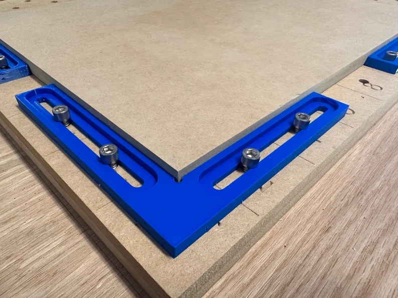
If you use a corner fixture like one of these. You can create a starting spot that you will only need to zero x and y one time then all the following pieces will only need to be z zeroed. This keeps two sides perfectly square every time and you only need to apply side pressure on two sides to hold a piece of material in place. This has been my go to setup for turning out lots of different projects in one day.
I’ve either seen your or someone else’s posts in that regard, and appreciate its simplicity.
I have my 1F mounted on a QCW with rolling/folding.
I may end up doing a hybrid version of this as an “easy button” solution to my problem, especially if the code is complex (I haven’t looked, yet…swamped).
I hate to admit it, but the easiest solution of them all might be to re-do all my tiling files to acknowledge my specific cutting area reality (instead of the generic information 1F posted that I relied on to build my models in Aspire).
As a still-relatively-noob CNC’er, I’ve found this issue is a crucial item with the BB (classic?) controller. Of course, if you never even get close to using the full area of your 1F, it’s all moot.
So I tried the G28.1 code in MDI, and maybe I didn’t do it right…
…but then I found this.
Visually getting x & y to zero (using the controller’s x button for the fine tuning) and then backing it off 1 mm (substituting my eyeball-data for its stall-home, then-back-off-1mm solution to define G28.1) seems to be the time-poor man’s solution. Since I’d be keeping the 1mm buffer in there, I can’t see any downside to doing it this way (other than the effort of manually setting home rather than just hitting a button).
I will admit that I don’t know what would happen if you answered “Yes” to the “Do you want to home the machine?” question asked upon successful boot-up. If it sets the existing position to zero in the x & y after doing the stall home for z, I would imagine it would be easy to clear and start over via the home button in the Axis Table.
Short of the exotic limit-switch setup WaywardWoodworker discussed above, I think this is a quick enough way to get a consistent zero position for people looking to max out their 1F workspace (especially cogent for tiling).
I am currently doing an epoxy project but too scared to try this while the project is in progress! I plan to give ti a try once I am done with this one though. I have been searching for days for a way to do this. I agree with Nogonav, this should have been one of the first things in any beginner video or instruction sheet.