UPDATE:
I machined the right hand side roll cover start to finish, and used that as an initial test of the cover’s effectiveness. It did a very good job of keeping the HDPE and aluminum chips off the top rail and ball screw. The bottom rail only had a few HDPE chips stuck to it. Given that I did not use any chip protection at all at the end mill during any of the machining I am quite pleased.
I installed the 2nd roll cover, and now the last design challenge is to decide on what I will do for a chip shield/dust shoe. I have a few new ideas, using a few different components - I just need to decide which design wins out and I will then order some parts.
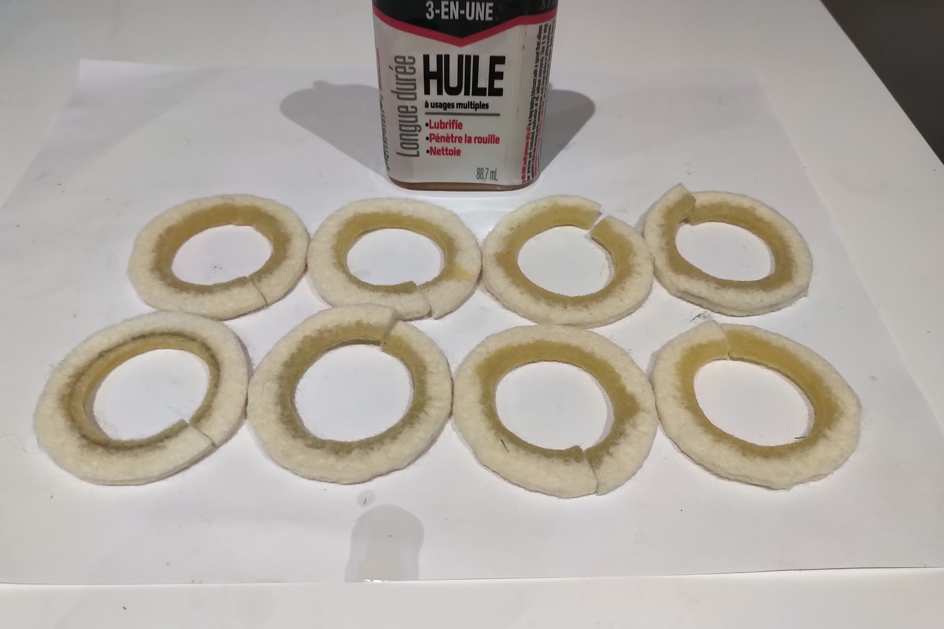
A long time ago I designed and 3D printed a solution to act as bearing wipers on the linear tube rails. I thought since I finished the roll covers I would try them out now as well to see how they work. They are in two parts, with a ring of industrial felt held against the linear bearing on pushed against the tube. There is a channel for a cable tie that holds the entire assembly together on firmly on the linear bearing. I saturated the inner edge of the felt ring with 3 in 1 oil, and will add more as needed. I will be away from my machine now for a week, so will share the results of testing them upon my return.
Here are some photos that help explain the above descriptions:


ORIGINAL POST BELOW
One thing I am always considering, and have for a long time, is improving the protection of the linear motion components on my Woodworker. The high wall aluminum panels that I made do a good job of keeping most debris off the Y axes, but a solution for the X axis gantry has not been as simple.
I researched many solutions over the years since getting my Onefinity - custom bellows from overseas, telescopic spring covers, and roll way covers - and realised quickly after getting a few quotes that I simply can’t afford any of the company offerings (I also was not convinced they would work, since there are pros and cons to each solution).
So, with more and more ‘successful’ machining experience to draw on, and my constant need to modify my machine, I have a finished prototype to test.
For those wanting more information, I have:
- A new reel on my IG page, which provides a very quick video summary of the machining process, parts, and a glimpse at the finished prototype on the CNC
- For those that don’t mind taking more time, I have uploaded two videos (Part 1 and 2) to my YT channel. These are best watched in order, as they are really one long video that kept crashing my old Dell M4800 - so now they are two
 . In the longer version I have added short captions detailing the F360 toolpaths, endmills used, and a bit more information on the machining and work holding used.
I have installed the roll cover on one side, and will evaluate its effectiveness at keeping chips off the tubular rails and ball screw. I will update my post as new information presents itself.
Here are a few photos that may help people decide if they want to take the time to watch the videos (many of these photos appear in both).


