If you unplug the motor and bridge the phases + and -'s together, youll see that it creates a brake. That’s what this board does.
How did you handle the 8mm to 3/8 difference in the shaft coupling the Masso motor to the brake.
Looked for a brake with a 8mm in/out shaft.
The one i got seems to be discontinued or something because the website lists it as unavailable
Hey Colin, hey Chris,
this relies on electric motors acting as electric generators when moved, so with the coils connected this way, when moved, it creates an electromagnetic force against the motion. This is a known effect. It works, if you tolerate a small amount of motion and the fact that there is a limit with this force. But it cannot replace a brake. To implement a safe stop mode as Emergency Stop, you have to ensure that at same time the motion is prevented and the motor is powerless.
I didn’t think it was a suitable solution. May address some of the problem, but wasn’t a solution…
My dog keeps barfing, so i stopped feeding him… problem solved…
Thank you for sharing your success, as well as the wiring diagram.
Just so I understand, the ES output from Masso was not outputting enough voltage to trigger the Masso relay input?
In your diagram, it looks like it is split, and one leg goes to the Onefinity box. Masso says you can connect up to 2 relay inputs to the ES output, but maybe what it connects to inside the Onefinity box causes the voltage to drop even more?
How did you add power to the Masso controller output port - I do not see that on your diagram?
Sorry for all the questions - I imagine after the time spent you want to leave this topic - I just like to learn as it may help myself or others in future projects.
So happy you got it working. As I said before, In my opinion I think it is a safe and solid solution that will give you peace of mind - well worth the time, effort, and money invested.
The output from the relay to the brake wasn’t putting out any significant power to speak of.
Like i said i was able to manually rotate the brake when it was plugged into the relay with a screw driver, but it was fairly difficult, likely causing motor alarms when trying to move. I wasn’t able to rotate it when it wasn’t plugged in. I was thinking there was some setting somewhere then i called my buddy and that’s when i hooked the multimeter up and came to the realization that the relay wasn’t outputting the power needed to fully disengage the brake. Now when i hit the estop i can hear it snap closed, and unlock i can hear it snap open.
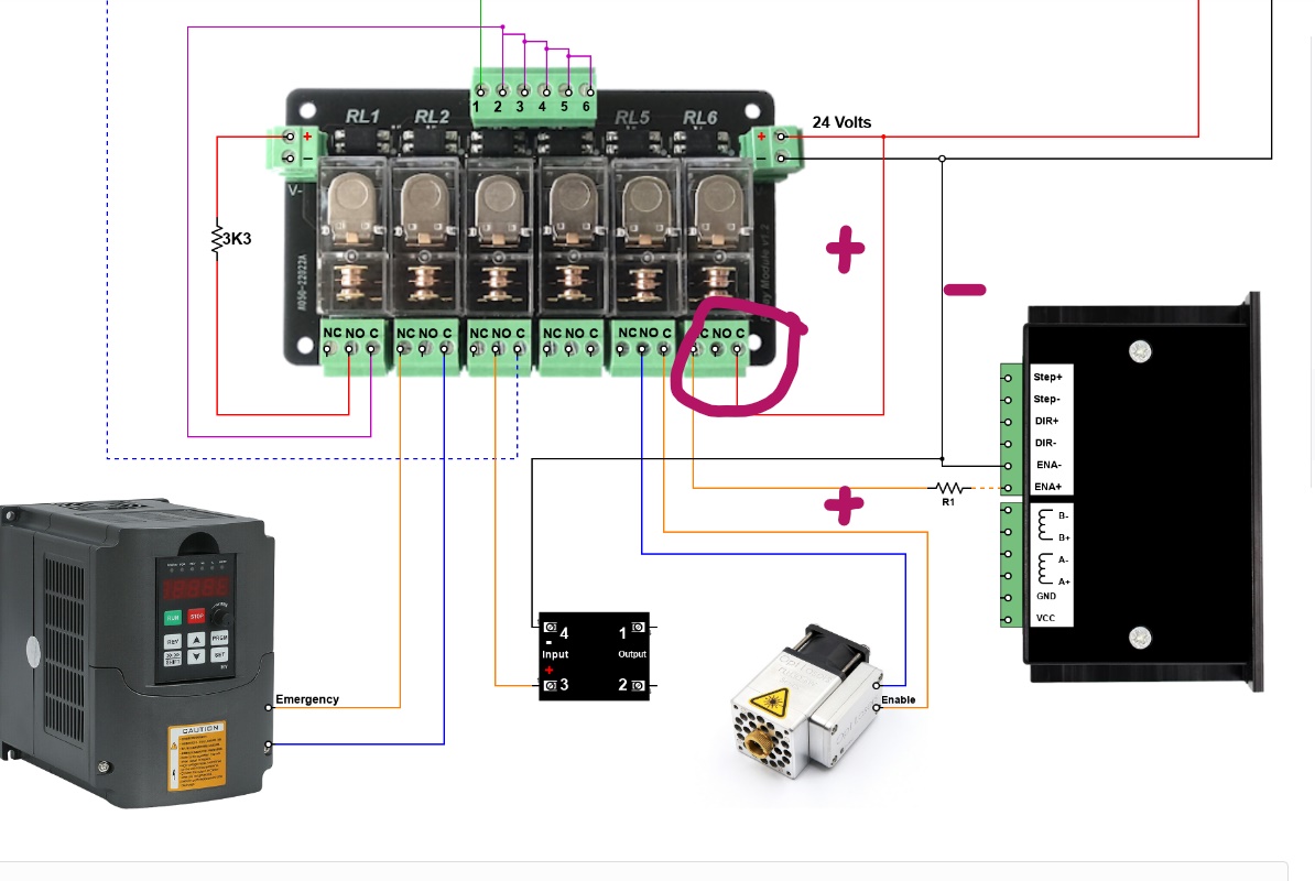
The es output port just activates the normally open/ normally close part of the relay. The way i added more power was the lower part at the relay where i added a jumper wire from the power input and plugged it into the common at the relay output, then the negative of the brake to the power input negative terminal. Maybe the 3a fuse was too restricting, i think i read the relay can utilize 5a. The relay signal comes in from the single terminal at the top, and triggers the relay to open or close which sends the power to the device
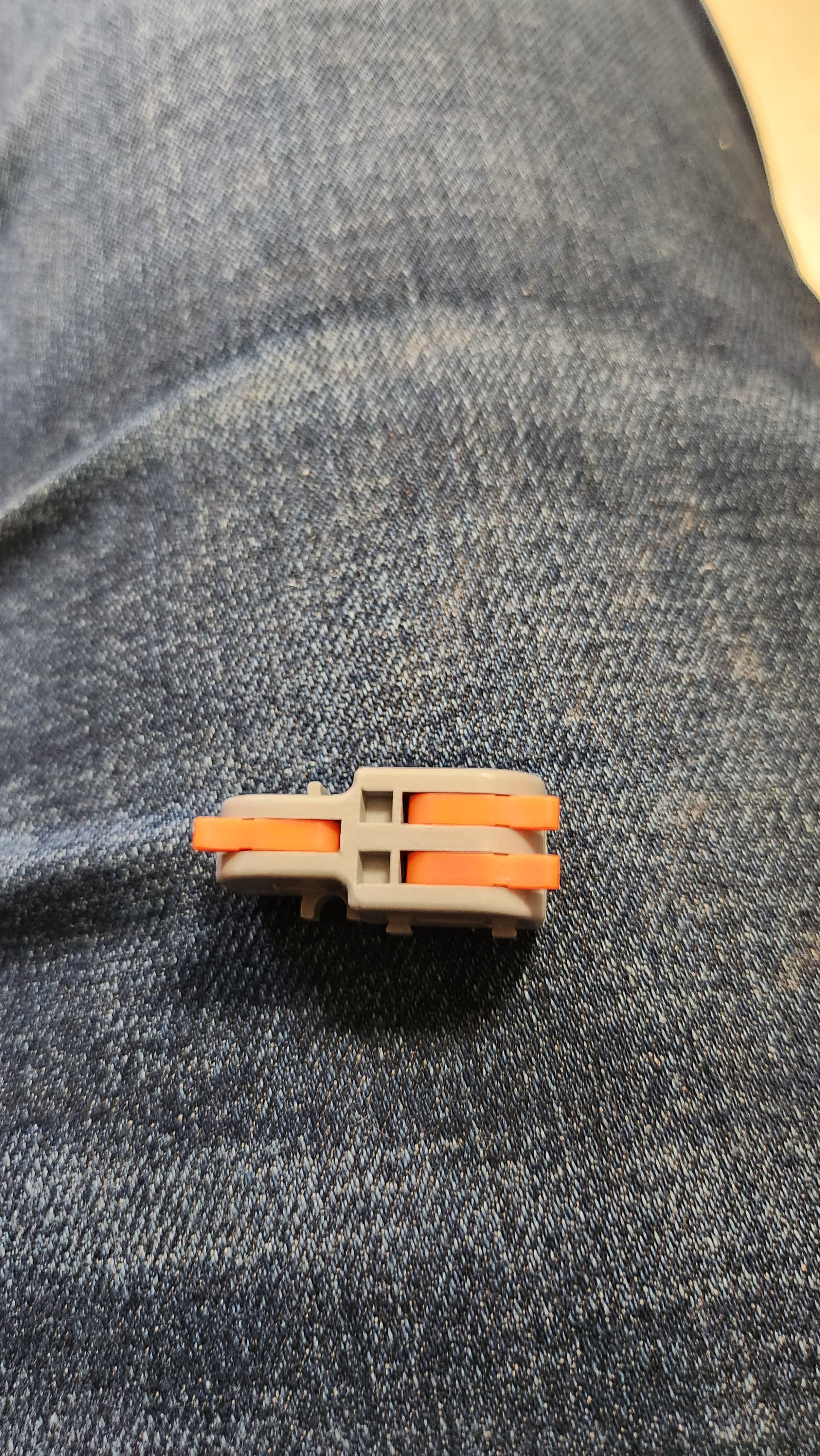
I found these and thought they were the coolest (and can be utilized in my shop build as well), so this is what i plugged the router and shopvac es output as it goes to the black box, the other one into the relay, and the single side going to masso… intent being i don’t want to lose functionality, even though it’s a function i don’t use. Not split but merge.
I’m not ready to leave it yet… but yeah, a big relief… i feel like the kids in South park and Make love not warcraft (3 min for relevant part, earlier for context)
Thank you for taking the time to answer my questions.
That what was I thought you meant. <I had tried to explain this in #108 above(my apologies, this comment was unnecessary ![]() )>, but I am happy you got the help to get it to work.
)>, but I am happy you got the help to get it to work.
I highlighted the example that ‘most closely’ matches your solution in Masso’s Estop wiring diagram - but it is for a driver enable circuit.
Sure, you’ve been very helpful and a reliable source of information. To deprive you of answers to questions for clarification would be sacrilege. Your contributions haven’t gone unnoticed, i promise!!
Hey Chris
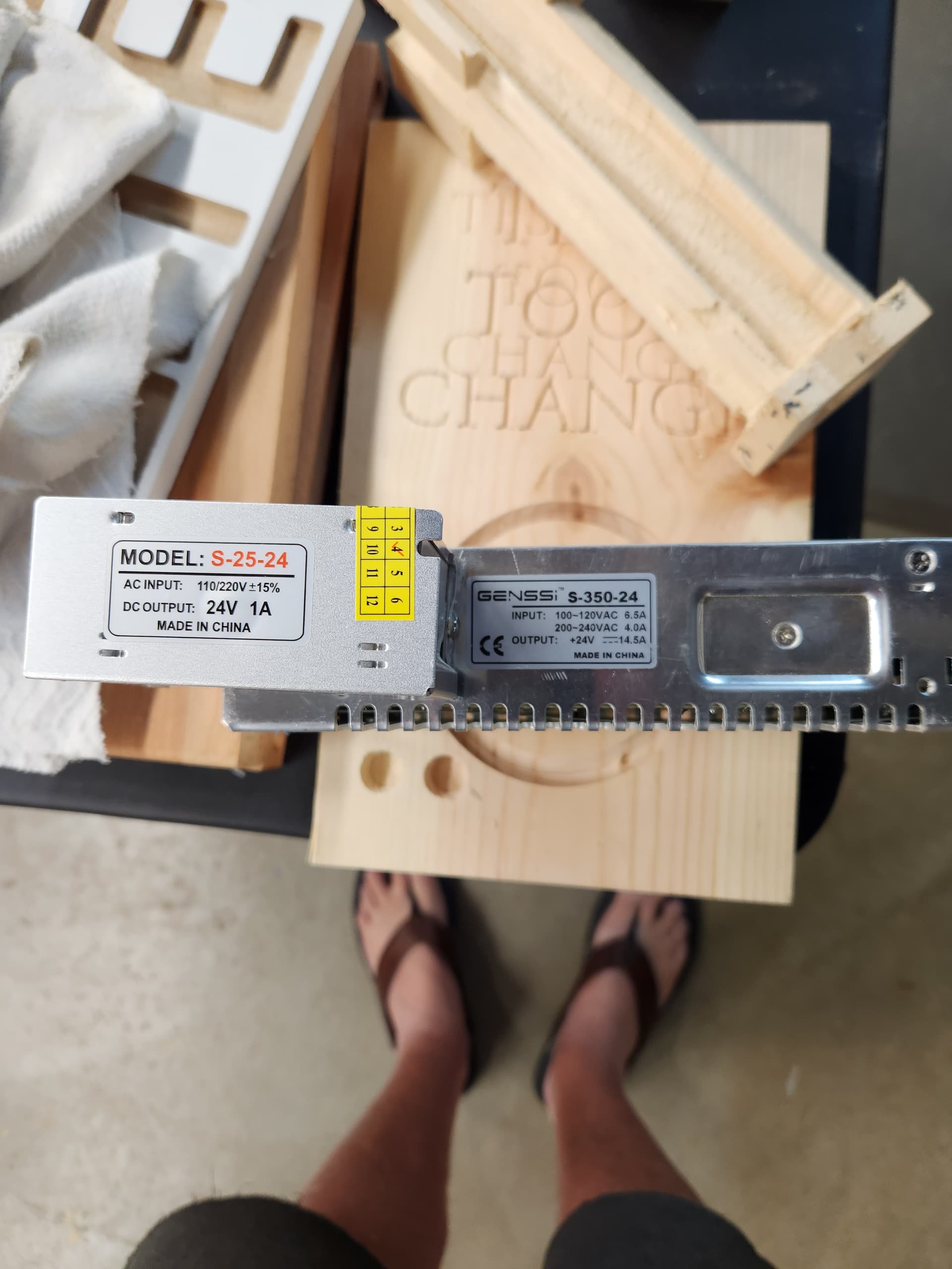
I have 2 - 24volt DC power supplies one is 1 amp, the other one is 14.5 amp.
You think i can get away using the one amp
On the ac side mine is fused to 1a, dc 3a so it depends which one. Mine puts out 75w
Couldn’t find a 8mm to 8mm brake so i had to go 1/4 to 1/4 , but ive worked out a solution to that hurdle.
Coupler for the z side, drill out motor side?
I’m tidying up now so wiring can be pretty and not all over the place like they are. While functional i could only swing masso so much and my power bank was just screwed into a sheet of plywood
Exactly except I’ve got a 8mm reamer instead of drilling on the motor side, just bought a 8mm to 1/4" coupler on z side. Already pulled the shielded 22 gauge wires and put them in looms to keep the elite look. Will 3d print enclosure for the power supply and might use plug connections. I’ll do pics when I’m finished.
??? 1F refused to answer what was available… and there is no 24v power supply in the black box. It’s a 36v that goes to a board before heading out to masso.
You could use a buck to get 36v down to 24 v, but I’m going to use a seperate power supply to avoid opening onefinity box. Yep front end brakes are expensive…
And there is no 24v power supply in the black box… it’s a 36v that goes to a board with a bunch of doodads and dohickeys… the motors are 36v
And i can assure you… it’s a 36v power supply in there. Open it if you don’t believe me
Check the motors
When i hooked up the wires for my 4th axis rotary i got 36 volts from the provided plug out of the black box. I needed 24 volts for the driver for my nema 17 rotary so i bucked it down. I am moving up to a nema 23 rotary and will replace that motor with a masso so i can get closed loop and get rid of the driver and associated crap…