Setting up a 1.5kw 110v spindle on a shoestring budget and having fun with the repurposing of parts. I am attempting to make this a safer spindle package than what Amazon sent me to plug and play. Please feel free to post pictures of your set ups and parts used.
I used some power cords that I found around the house and soldered ring terminals on the individual wire ends. Inside an old gutted PC case I drilled a couple mounting holes and installed this EMI filter Noise Suppressor Power EMI Filter Termianl Single-Phase Line-Conditioner JREle AC 115/250V 20A CW4L2-20A-S. As well as my VFD into the pc case.
You can see where I had to file down the ring connectors in one of the pics.
Work in progress not sure about using the 3rd wire on the Load power in to the VFD? I just grounded both sides, filter side to metal pc case and VFD side to the metal plate on back of VFD that makes connection/continuity to the ground terminal on the front right of VFD as tested with volt meter. I am saving that front connection to ground for spindle cable ground wire.
Next is the male power in plug and a on off switch to the VFD. This will be mounted in the old power supply box of the pc and have the power enter in the stock pc location. I have the stock PC power in plug 10amp and a 12amp fuse but going to look for something else…
A thought for you and your design you might want to consider is make sure you can see your vfd display once.installed. i find that checking that the vfd has not tripped (or even has been switched on ) useful.
I don’t see where your VFD is actually grounded. i.e. the incoming power does not look like it is connected to the PE (grounding point on the VFD). Also I would get a grounding bar and isolate it from the PC Case if you are going to have multiple things that you need to ground. They are only a few bucks at the big box hardware stores. Finally, if you plan on enclosing the everything you need to consider getting some airflow/fans in that case.
BTW, What you describe as grounding is not what I would call grounding the VFD and spindle. There may be some round about way that it will ground but i would tie directly to the PE on the VFD. for example incoming power green to PE and the spindle (Wire#4 to the same PE screw found on the right of the VFD. (Not sure if that PE is actually tied to the VFD frame that you are referencing.
Thanks for the input Dean, much appreciated.
About the incoming power and ground, my emi filter has 3 leads on incoming side and two on Load side, where should ground attach if the opposite end is attached to VFD PE connection?
What I did was attach an extra ground wire to the line ground on EMI filter and then hooked opposite end to PC metal case as star ground along with a ground wire to the frame of VFD and back to the star connection.
Please let me know if there is a flaw to this wire routing, thanks
Exciting stuff tinkering around, planning a spoil board and t tracks on the way. Never stop learning and always interesting things to try out. Thinking about a trap door set up on the table. Have a great Monday everyone!!!
This is similar to what I would draw up. Remember your cable coming from your spindle should also be link to the PE ground. That should be Pin 4 and then UVW should connect to pins 1,2,3 on the Spindle cable. Not sure if you have already confirmed that Pin 4 has continuity to the spindle casing. I ask because many of the Chinese spindles do not have pin 4 connected on the inside of the spindle casing. I was lucky and it was already connected.
I have my double shielded spindle cable ready on the VFD side but waiting on a connector for the spindle side.
No luck here on the ground of pin 4, when I put my meter to the pins and the spindle case I got nothing as far as continuity between the spindle and pin 1-4…lol I will be opening it up and making the connection soon.
I did get lucky and found an extra #4 collet in my spindle. At the same time made me think someone else had already played with it and returned it forgetting the collet.
Found a few more scraps in the bone yard that might help with this build. Nice clean socket 15a 250v and a little fan to build up positive pressure inside the PC case. Found a few cable clamps, gromet, and cable mounts that wrap around the exposed shielding of the spindle cable.
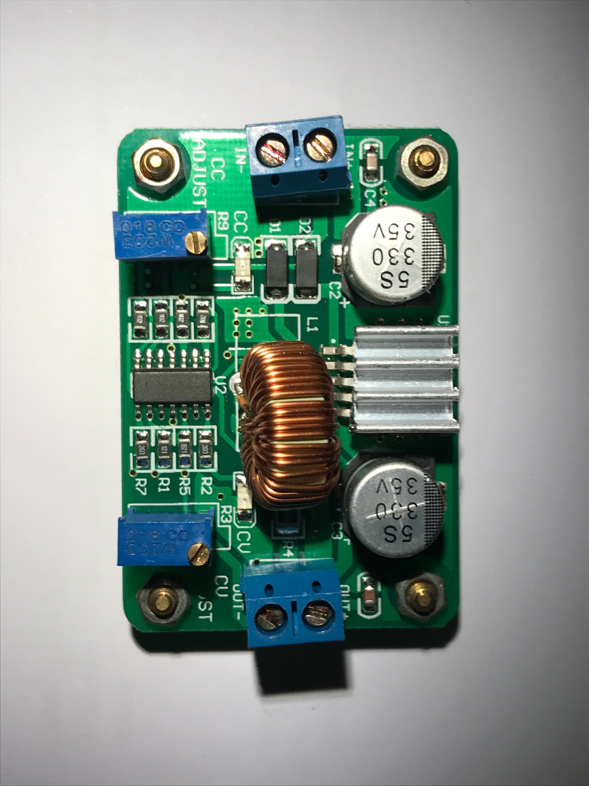
Found a DC-DC buck converter input 5v-30v output 1.25v - 26v commonly used as LED driver power supply. Not sure if I will use it or not but was a good find…lol
Off to the soldering station, hopefully things are going your way!!