X-Offset problem with 2 sided carve on Fusion 360

Hello dearest forum readers,

Tech spec: Foreman Elite, Pwn 2.2 air, RapidATC towers, tool setter and contact block.

Experience: 8 years self taught career engineer in manufacturing, first experience with CAM since high school and first project on the machine.

Problem: On carve completion X axis seems to miss by up to 1/8 in offset between flips. It is variable between occurrences.

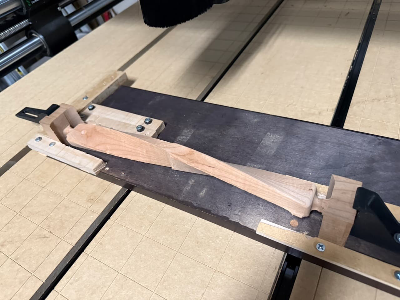
Stock Setup: I use BOW low pro clamp system to hold my stock, drill pin holes in the stock half way. I remove the bow system entirely and insert the 3, 0.3 in wooden dowels in my waste board which I also cut with the same program previously. I flip the stock, place it on the pins and press it down till its flush to the waste board and check for any rocking. I run the pin carve again.

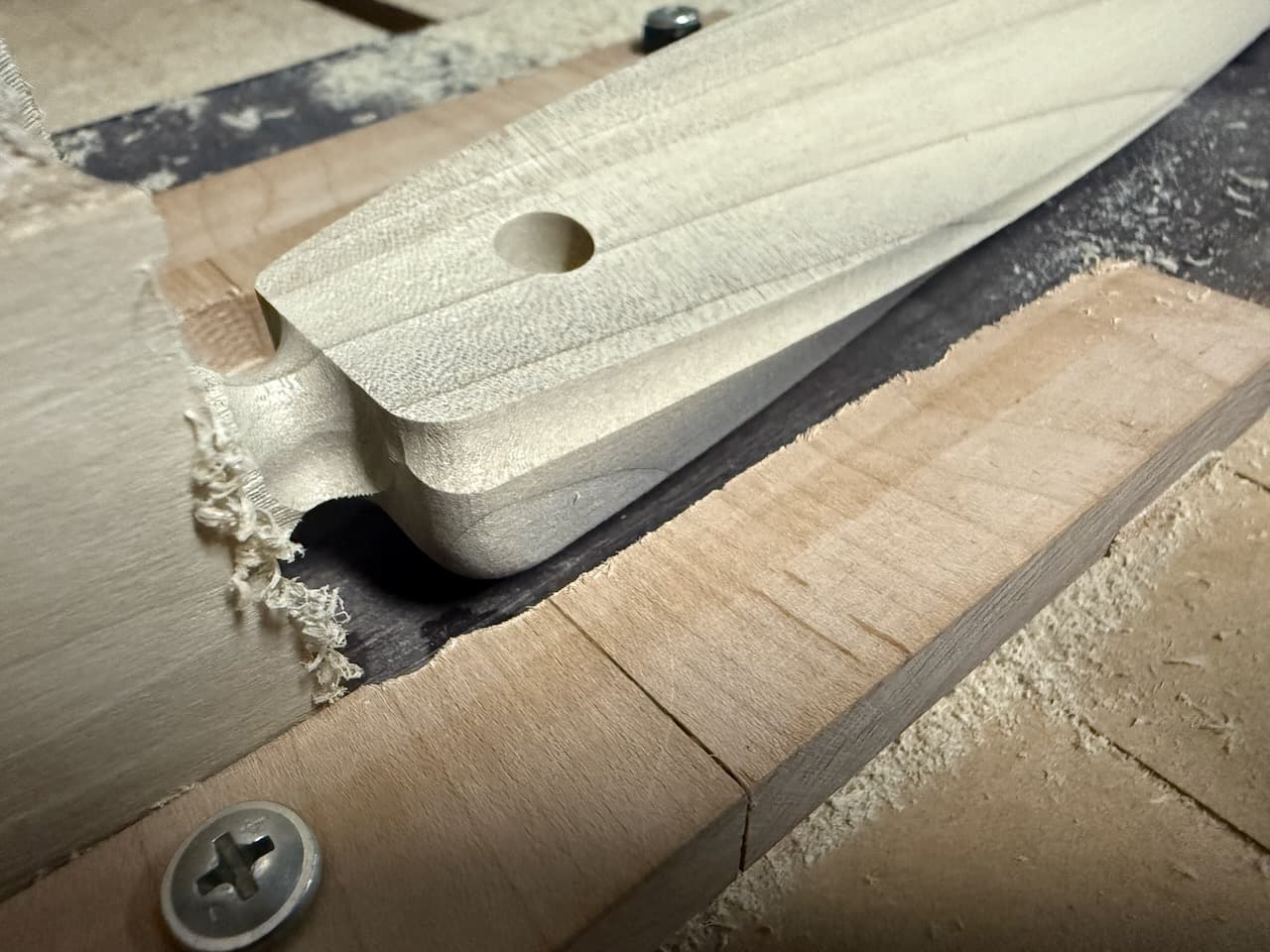
Problem: I run my back program first because it does not cut as deep and I have my tabs in the front carve program. I flip my board on the pins, again firmly press it to the board and check for gaps and rocking. after the front face carve completes, its clear that there is an offset on the X axis specifically. See Photos. Each side of the carve uses 3 different tools changed automatically by the rapid ATC. Tabs are the LAST thing I cut so I have maximum strength in the part until the outline clearing.

(I have been having grip problems on the 1/4” compression bit where its pulling into the material. I found the cause to be debris in the collet and placed blue tape over the collet to help as well as enabling 3rd strike in the ATC. I also lowered my stepdown to 3/8”, and will be adding a roughing tool soon so I can save the compression for finishing moves.)

F360 Setups: Using front left corner as per standard on both sides.

Homing/zero: I don’t change the zero from the top front left corner of the stock in this entire process. I do not rehome my machine at all during this process. I DO check to make sure the zero location is still accurate between steps by driving the bit to zero with step moves and visually inspecting.

Please impart your wisdom on me, oh great people of the forum!

Thanks, <3

Don’t know if this is your problem but I had to calibrate my X, y, and z travel distance. I recall my X was off about 1/8” in over a distance of about 24in.

2 Likes

Have you checked to ensure your machine is completely square? Given the issue is when the piece is flipped, that signals the machine is a parallelogram not a square. There is a lengthy post about this in the forums.

Note: it seems, which is news to me, the originator of the information has been suspended. Huh. Interesting.

-Tom

2 Likes

I use Fusion and have worked out a system for 2 sided machining of my Eaves House Bird inspired wooden models. I use steel locating pins in the stock, similar to your method, but in my setup these pins are screwed into an aluminum plate. After facing both sides flat, the first OP side is zeroed to the stock top, front left, and two locating pin holes are machined.

Where we differ is the 2nd OP side, which after placing the material onto the pins, I zero to the Pin #1 location (my CAD WCS zero). My SMW fixture plate typically remains on my table, and is dialed in with my 3D probe - the plate, and pins, are typically within hundredths of mm in line with the X axis as I normally only mill aluminum and want tolerances as tight as I and my machine/instruments can get.

So, perhaps using one pin location for zeroing the 2nd OP - and changing this accordingly in your CAD - might be an interesting experiment to try.

If interested, here is a link to a video I made which summarizes some of the process.

https://youtu.be/aU59bioGUFA

2 Likes

Is the X axis the axis of rotation during the flip? The same axis that the pins are aligned on?

1 Like

Working on trying this, I hadn’t even considered it. given the inconsistency, it doesn’t completely fit but its worth doing regardless. found a post with some good content on this, need to order a measurement device I actually trust like that.

1 Like

I’m absolutely square but it was an interesting suggestion!

I actually read your post prior to making this one as well. Admittedly I’m not sure how I would zero accurately to a round pin, or how exactly that makes a difference? (Not trying to sound rude, I genuinely would love to understand the thought process). I’ve been debating upgrading from my cheap dowel pins to steel pins to remove some potential slop, I’m concerned that could be some wiggle. Going to experiment adding double sided tapes and CA Glue too to be sure.

Pins are in a Y Shape configuration and I’m rotating on Y-axis. Although I realized if I switch to two pins and just make my stock a bit longer it should lead to less concern with width variation of the overall stock, so I plan to pursue that down the road, just having two pins in line in the middle of the stock.

Do the pin holes line up properly on both sides of the stock?

2 Likes

yep, i’ve made sure of that. was my initial concern. i just got some steel pins in today so i’ll be working to try updating the pin layout with those.

1 Like

Perhaps give your probing sequence some attention.

Are the dimensions of your probing block accurate synchronize with the corresponding setting in Masso?

Are you probing with a tool diameter that does not correspond to what is set in Masso? Check the tool table, and probing screen for these.

Are you probing with a tool that does not make contact with the probing block when it is exactly 1 radius away from the block? (Some end mills are only the full diameter on the cutting edge… )

Is your reference position on the CAM side set in the right spot? Silly mistake.. but I’ve made it several times.

1 Like

In CAM, are your pins centered in the modeled stock along the x axis?

The pins determine the physical realignment of the two sides. You need to make sure that the origin in both CAM setups actually aligns with the position you zeroed to. For the first setup, it will necessarily be aligned since you carve from your zero. In the second setup, your physical zero point is unchanged, but the zero point in CAM could be at a different position relative to the pins if the setup isn’t symmetrical. You could imagine a really exaggerated version of this effect by placing your pins way off to one side in the stock and zeroing from the front and back stock corners.

Hi Webspells,

I had/have a similar issue as the one you’re experiencing but, I preface that by letting you know I’m fairly new to this hobby. I got my Elite Forman setup around July this year along with the learning curve of multiple softwares including F360, Carveco Maker+, Deskproto and several others I’ve played around with, it’s been drinking from a firehose to say the least. That being said, please take my experience with a grain of salt.

I’ve been working on testing different pieces that involved two sided carves. Similar to your issue, mine is about a 1/4” discrepancy carving with a 3/8” bit. I tried different methods similar to you; For alignment, I tried placing pins (dowels) in corners of the stock, running along center of the stock with model being centered and finally setting up a jig that kept the stock in position when flipped (I think any one of these methods for alignment work). With each of these methods I would always check the work origin once flipped and with every method it aligned correctly (at least within a tolerance I was good with ~1mm). This is when I realized, for me it wasn’t the alignment that was causing the issue. I eliminated the possibility of Onefinity being out of calibration because board-2 of the two boards (models) I was carving came out perfect, it was only board-1 I was having issues with.

Board-2

Board-1 multiple test carves.

To give a little background as to why I came to this particular conclusion, my carve involves two boards that are to be mated together, in this Fusion360 project there are two bodies from the same model, when going to manufacturing, I setup the stock as a fixed size and then in the setup of the second side I chose “from preceding setup”. I did the same with both boards (models). I think here lies the problem and I’m only speculating because I’m not experienced enough in F360 to validate it or to troubleshoot how to fix it but, I was able to come up with a work around. This may or may not help you since you’re only working on one piece and my issues only happens to one of two pieces (models) in my scenario.

In F360 in the Milling setup, Instead of using the “from preceding setup” i switched to “stock from solid”. There’s a process to making a mesh that you’d export from your stock left over from the first side then import it as an .stl to use as your stock for the second side. There are plenty of videos out there that can explain the process much better than I could do here, I would highly suggest taking a look to see if this might help.

After doing that change, the carve on my board one came out correctly, aside from about 1mm being off that I’ll chalk up to me not being as precise when going over this troubleshooting setup again and again, my hasty jig may have gotten a little worn out.

Board-1 before (left) and after (right) stock setup change.

Top board-1 prior with issue, middle board-1 after change in stock setup, bottom board-2 first carve.

I hope this helps,

Gil

2 Likes

I appreciate the perspective, these had occurred to me and I validated. I’ve even gone as far as using a steel pin in the collet when referencing my tool setter, and doing it manually. both lead to this offset result. my cam was referencing bottom left on previous runs. however i need to model my pins in and give the pin reference TMToronto mentioned a try.

1 Like