Box Joints and Dovetails

It’s about 1.25" from the front of the bracket to 0,0 spindle position.

Mike, I just want to make sure I understand what you’re saying. From the front of the rail mounting foot to the spindle 0,0 (down the Y axis) is about 1.25"?

Yes, that’s correct. Mitz posted this for me a while back: Dimension question - front of machine to "y0" - #4 by mitzpellic

2 Likes

Perfect, thanks Mike. I went from paper sketches to digtal mock-up in Sketchup tonight. The table is just big enough for the footprint plus an inch in all directions (I have limited space). The machine will be installed “flipped” with the motors towards the front. I made the design with 2x4 and 3/4" MDF in mind for materials. Vertical and horizontal tables are two layers of MDF. The waste board is 32"w x29"D and should allow for 2" for vertical milling thickness with an extra inch for bit pass through. I’ll sacrifice the 3" of Y cutting area to maintain the permanent vertical table. That’s my thought at least…for the first draft.


6 Likes

I almost did something similar - but in the end decided on a removable insert. Someday (not soon), I hope to get a rotary 4th axis that will fit in this same spot.

A removable vertical insert also allows me better access to below the table top for storage - something I really need.

1 Like

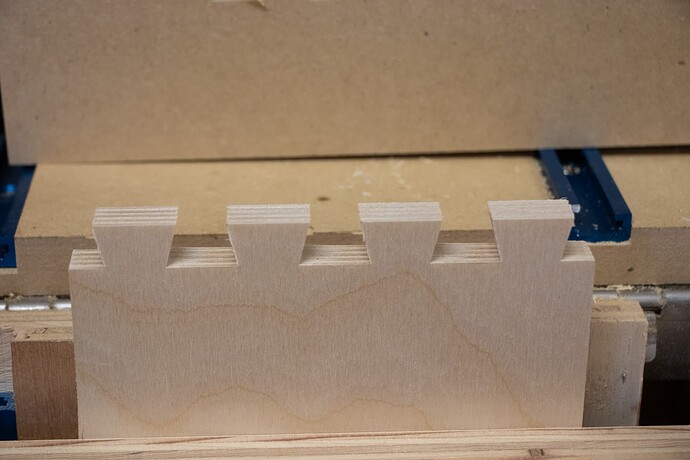
Dovetail success! Put my new drop-in vertical fixture to use, made my first dovetail box drawer today. Really happy with the quality. My setup allows me to rotate and swap boards without needing to touch the 1F’s settings - ran all of the tool paths with the .25" down-cut bit first, then re-mounted the boards for the dovetail bit. Worked great!

Had to tune the settings of my probe - it was off a little bit and was messing things up. Accurately measuring the thickness of the plywood was also needed. Used a .005" clearance on both the pins and tails - these things fit like a glove, just a light tap with a hammer to get them to set.

Clamping the backer boards eliminated tear-out, at least I could reuse them for all the cuts on this box.

Need to fine-tune the cutting paths in Fusion - the 2d clearing passes work, but I think a simpler approach would be faster - something to play with next.

Here’s some photos of what I ended up with:


16 Likes

Nice work Mike,
Thanks for sharing the info
Hopefully my machine will ship soon and I can get started

Those look great Mike. Nice job.

How did you set up your parameters in Fusion? Do you have it set up for different stock sizes, number of dovetails, and overall dovetail size or is it a lot more in depth than that? Is it just for through dovetails at this point?

I do have parameters that drive stock thickness, and board dimensions (length, width, height). Also have parameters for the number of pins, the width of the pins, and the angle of the dovetail bit. I followed this video tutorial to set up the main box and parameter-driven design, and then made a manufacturing model to build out the tool paths: Fusion 360 Woodworking: Dovetail Joints - Make them the easy way! - YouTube

I sold my Porter-Cable Omni-jig but now I’m wondering if I should have hung on to it and scavenged parts for a vertical board and clamp system on the Onefinity.

I downloaded the JointCAM demo software and will give it a try. Making box joints and dovetails is something I would like to do with the CNC.

2 Likes

I’m still new to JointCam and there’s definitely a bit of a learning curve between the software and setting up your workpiece. I made my first (non-test) half blind dovetails tonight. Not perfect but as good or better than I could do on my dovetail jig. This will be much faster than the jig once I get the hang of things.

Which will eventually become one of these…

4 Likes

Excellent. Please keep us updated with any findings, troubles and top tips. I am also just venturing into Jointcam and joints.

When you get a chance could you share some photos of your table with the removable section. I’m looking at how I can incorporate a removable section into my table which I have yet to build, just have the 44x64 Kreg frame and legs assembled so far. Still need to build the top.

I have the Journeyman coming so I figure I can give up a few inches along the front and still have a 26x48 solid surface with an 6x36 removable section up front.

I would like to add a fourth axis in the future when available. But I thought I read on here the Onefinity controller does not support that correct? So would have to move to a new controller.

Hopefully these help:


3 Likes

Where did the vertical board come from in photo #4 ?

I mounted using a piano hinge but It’s not there in the 3 previous photos.

Maybe you were in the process of building this when you took the photos.

The removable section looks to be about a foot deep.

If you look closely you’ll notice that the top board is on top of the original wasteboard - I created a 2-piece unit tied together with a piano hinge - I just drop it on top of my existing wasteboard. I created a pair of spacers to ensure I can get everything square. Takes me less than 5 min to convert back and forth.

The removable section is about a foot deep - which is plenty of room for anything I’d want to put verticle and also allow for clamps.

2 Likes

Ok, I see how it works. Very nice. Just pull out the flat section and drop the hinged board on top of everything and let the vertical section hang down and you clamp it in position.

This is along the lines of what I want to do but my front rail will be the front upper rail of the Kreg bench not a 2x as with the bench you built. Not saying one is better than the other just a different approach as I didn’t feel like building anything right now. I have my main shop all torn apart and rearranging everything and it’s a mess. It would be difficult to build anything in there right now plus I’m busy finishing a project for my sister and getting a couple Christmas presents finished.

1 Like

Your shop looks like mine!

:slight_smile:

I recently retired - I was supposed to have “all sorts of time” to clean and organize - still definitely a work in progress…

There are lots of different ways of approaching getting something held verticle - for me, I didn’t want to permanently lose space, and wanted to ensure everything was rock-solid when I wasn’t using a verticle piece. I’m about 95% of the way there - I just need to tweak my CAM a little, I’m relying too much on getting an exact measured width of a board (to allow it to flip and still maintain a perfectly symmetrical cut).

Good luck!

1 Like

I have been thinking about going a different route. I have been considering how I could permanently fix a vertical clamping surface that could be adjusted if need be for square and have a removable section above it that would be removed to access the vertical workspace.

My shop is usually much neater than that, but right now 1/4 of it is cleared out of everything as I run some additional DC piping, gave the wall a fresh coat of paint, add some storage, and rearrange things along two walls of the shop.

1 Like