I’ve got a elite forman with the redline 80mm spindle on a QCW.
I did have the tool setting setup (never used) on the rail
I did get the ATC and setup the wiring, but before running all that to install, I figured I should level the spoil board now that I have dust collection and all the pieces.
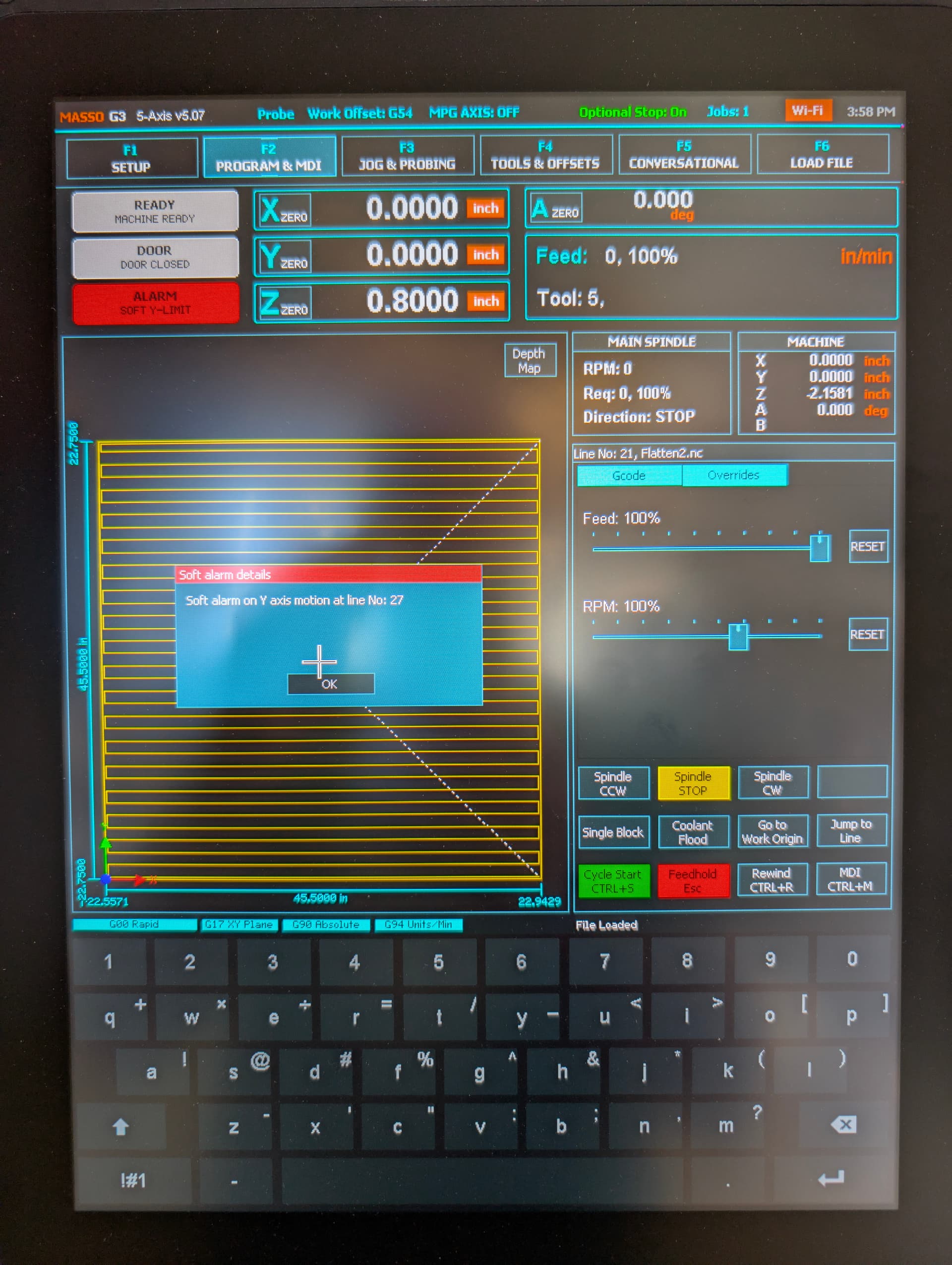
I’ve been watching and re-watching ton’s of videos on vcarve and how to do this.. for the life of my I cannot get this to work and keep getting the following error.
disabled auto z tool… what am I missing here.
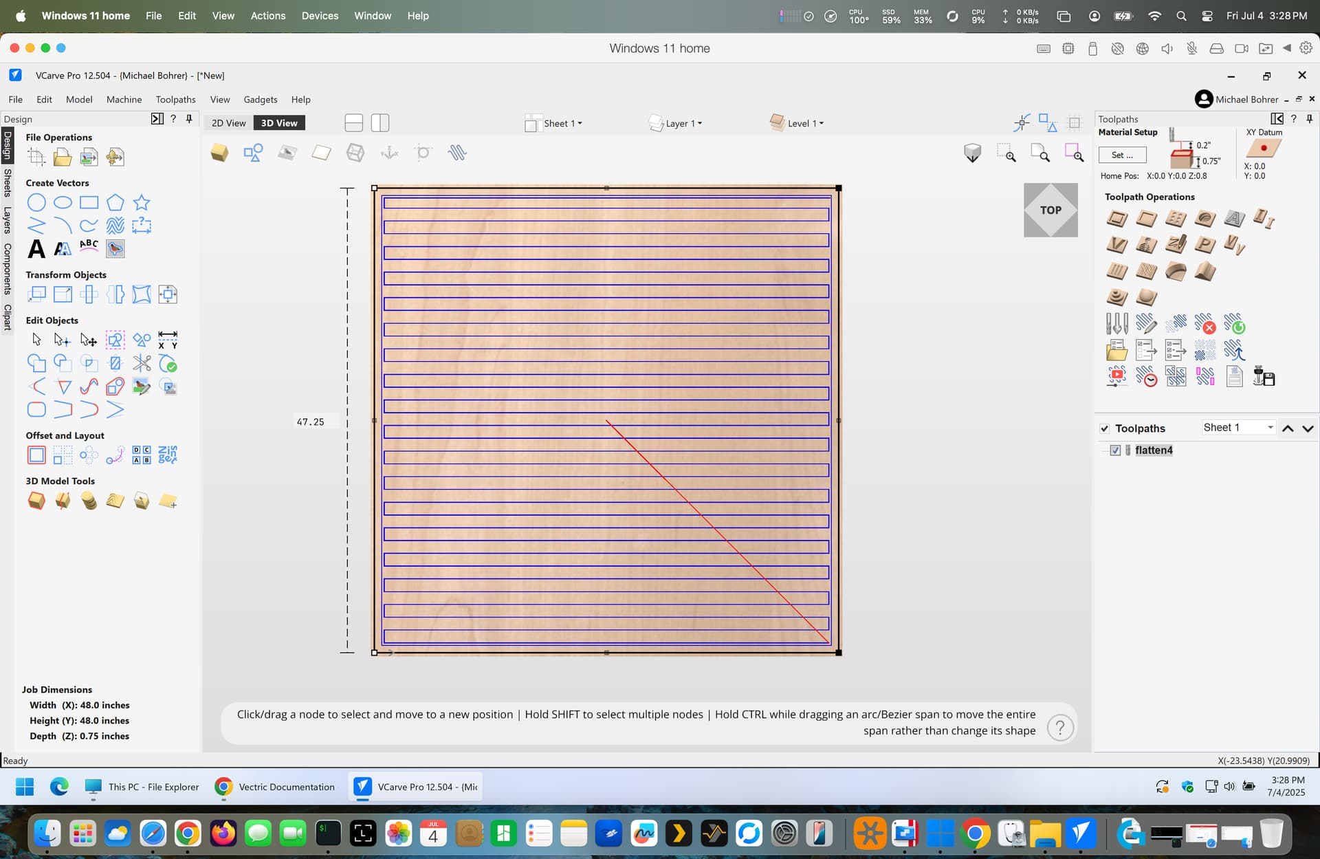
project is 48x48 with vector at 46.5x46.5 using a 1.5in flattening bit I’ve setup.
I do my spoilboard leveling in 2 steps (don’t know if others do it this way)
I manually check for the lowest point on the board with a block, an end mill and a piece of paper in 5 spots (the corners and the middle)
Then I manually run the outside perimeter 2 inches at .005 lower than the lowest spot.
Then I run a spoilboard program to just pass the border. Never get an alarm.
Also your gcode N28 shows a depth of .2" then the remainder at .003?
Sorry I misread that it positive .2 clearance.
Was your job setup for top of surface?
My job was set up for the material surface where I did the paper method for the z-axis zero and then set a depth cup of -.03.
Did the xy 0 after homing it.
I think the issue is something with the setup of the actual file parameters. I entered 48x48 for the surface and then drew a vector at 47 and 1/2 in both the x and y direction and then set it to raster and I continually got errors..
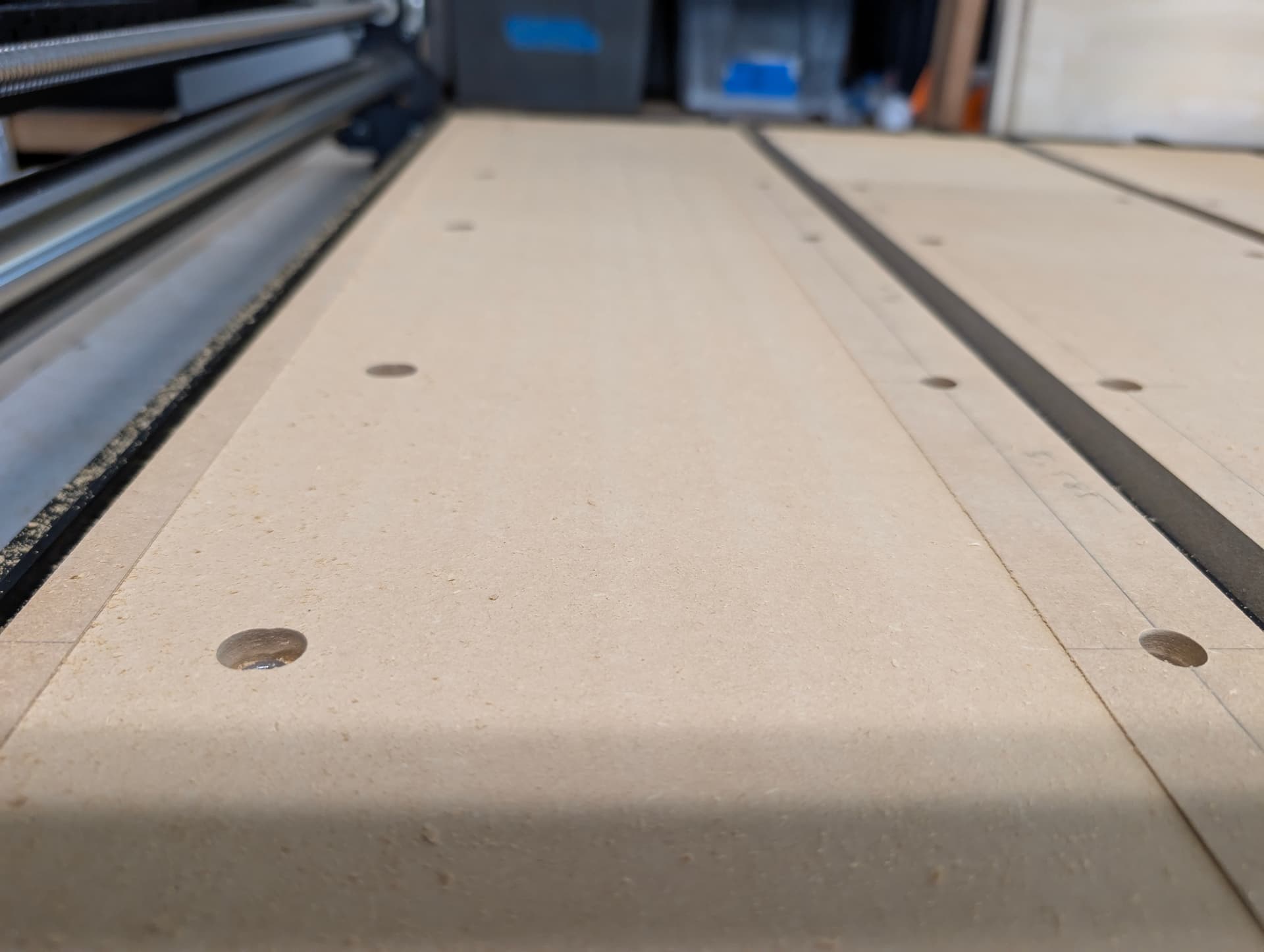
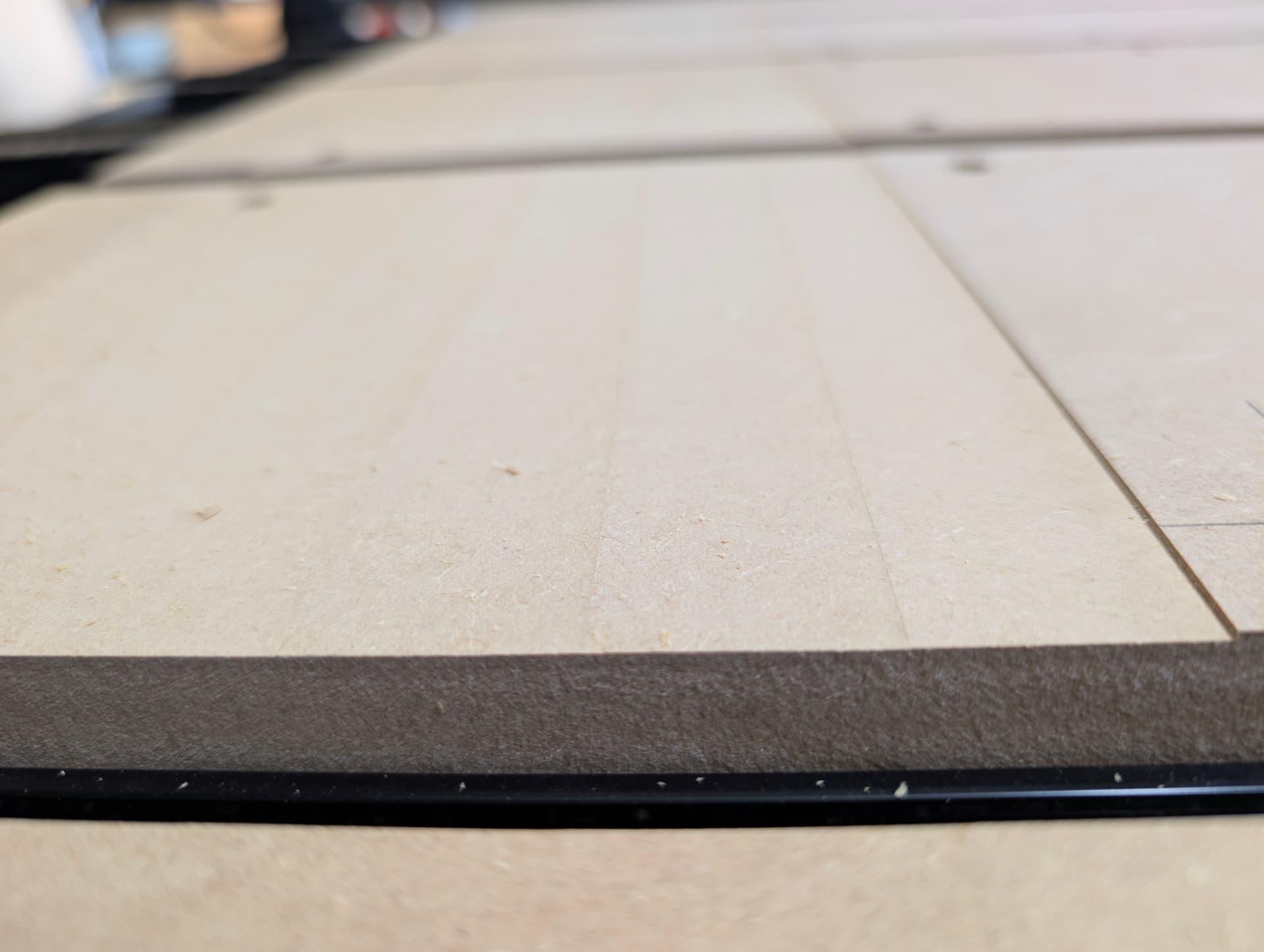
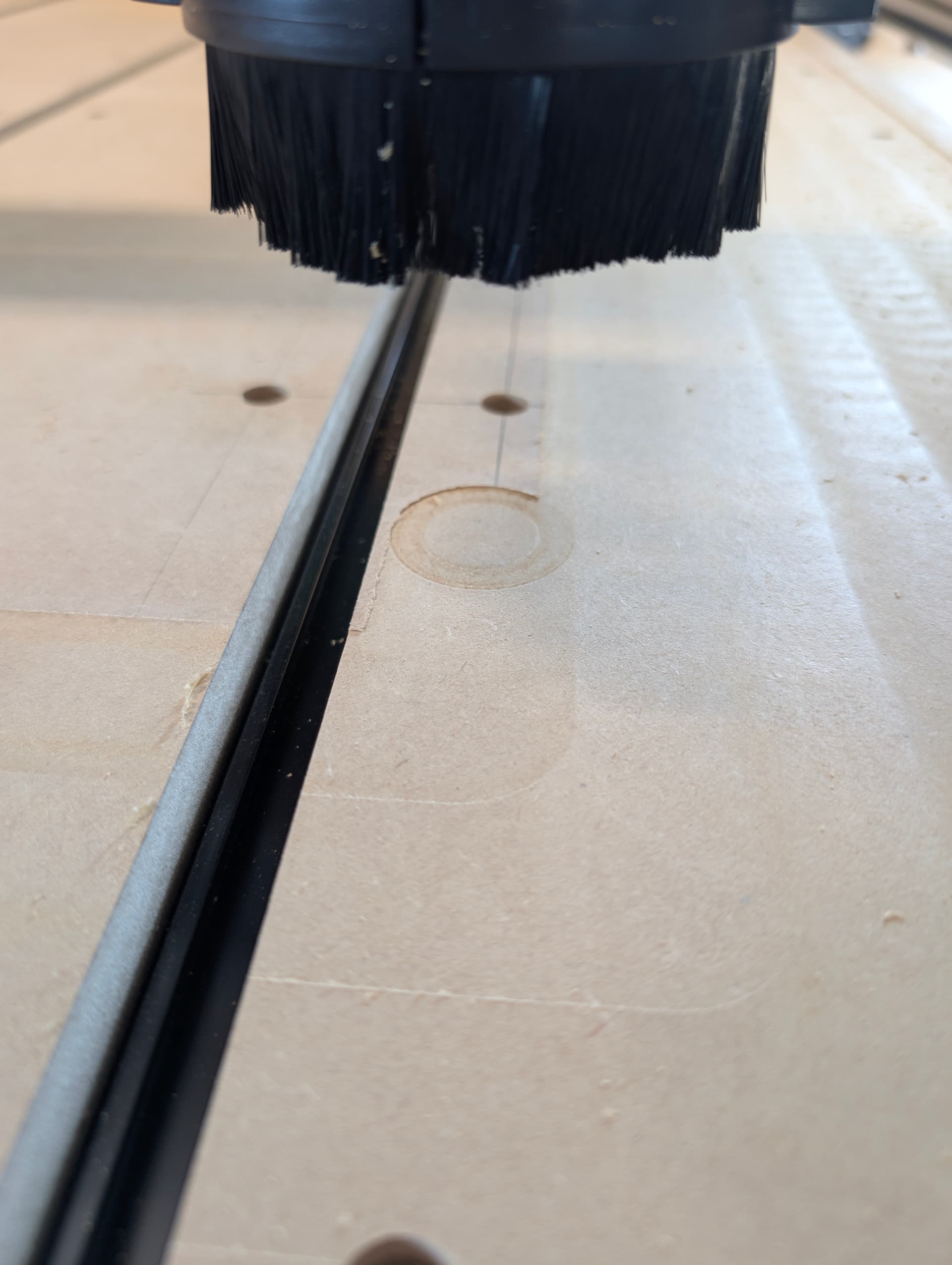
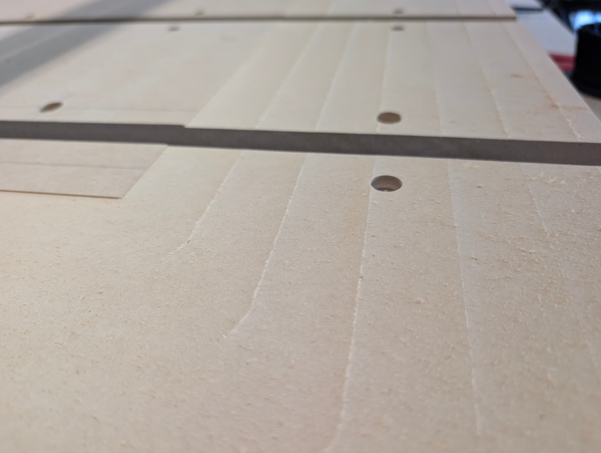
And then found that there is the F5 conversational method to do face milling and filled out the materials there and the same depth of cut etc. And the machine did run four loops around the spoil board at the right depth. The y direction is level and smooth but my x direction seems to have a little pitch in it. Leaving a small ridge in between the x passes. This issue with the x direction is more noticeable at the front of the qcw on the spoil board that it is on the back.
Trying to work through what I should be checking to fix that ridge issue
I have not, this is literally the first time running the unit after getting the atc and dustboot.
If I’m describing this right, when standing at the front front of the CNC, and the unit is traveling in the x-axis direction. The milling from the surfacing bit is deeper at your belly and lighter moving away from you… so it’s tilting inward toward me, meaning the bottom of the z-slider should shimmed out. it looks to be about 0.10mm using a shim, so .05mm being half the distance.
In reading some more, there’s tramming bolts on the unit? so I shouldn’t use hvac metal tape or something to do this movement? just making sure I’m using the machine and it’s adjustments appropriately.
I made a “tramming tool” out of a strip of wood as described in this video, which made it easier to see where the problems were: https://youtu.be/GVpq96KFfvk?t=351
I looked at the digital manual for my elite foreman and it lists micro tramming once, but no other place. I thought there was something within the unit itself that could do something like 2/32nds… I’ll give the dual dial indicator on a sheet of glass method (similar to what you listed in the videos, thank you.
maybe I’m over thinking this, but what’s the order of operations for just starting out. Without tramming or doing anything.
Mill surface fully
Tram unit
Surface again
I got the SST dual indicator, flat piece of 1/2 glass, was about to begin the process and noticed pushing ever so slightly on the QCW frame I would move like 5 thou… I know the bars are level (big level between diagonals of the Y Bars and even the table, checking in both directions in an X, shows the table and bars are level.
so if the top of the cart is level, qcw is level and bars are level… is the QCW really that sensitive? I mean a single thick glueup in the middle of the QCW will flex enough to negate the tramming?