Home, zero, load, run then z hops to new zero

I recently purchased a slightly used x-35 Woodman. I have used successfully used it to cut a few simple projects. I am using Fusion360 for designing and simulated projects appear correct. On my latest project, I start the machine, home it, then zero it on the work piece. Once I load and run the program, the machine moves to the right x/y, but the z goes positive and then appears to set a new zero ca2.5” above the work surface.

Attached are a few photos and the Gcode for reference.

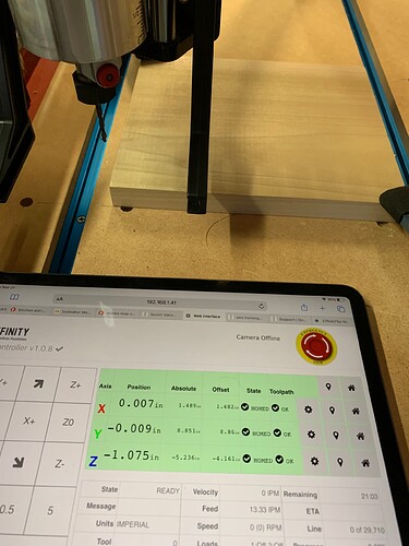
Homed and zeroed

New min z after run attempt.

Visual of the gcode (each tool is a separate file)


Gcode
Gcode - tool 1

Video link at the start of run:
iCloud

Any suggestions about what I am doing wrong?

I believe I’m having the same problem. I’ve been working remotely with @stradibarrius, helping him learn Fusion 360. He’s had numerous problems with cuts not coming out as expected, almost always with the Z coordinates being off.

So today we had a Zoom call at the machine for the first time. He homed, zeroed X, Y & Z all exactly as modeled. The Z-zero is at the spoil board, bottom of the workpiece (which is ~17mm thick). He showed me the bit position and the tablet screen showing Z=0. He then moved the bit ~100mm above the workpiece, put on the vacuum brush, loaded and ran the program (roughing w/ 1/4" flat end mill). Here are the first few lines:

N10 G90 G94 G17 G91.1
N15 G21
N20 G53 G0 Z0
N25 S10000 M3
N30 G54
N35 G0 X-106.409 Y71.02
N40 G43 Z34.43 H2
N45 G1 Z24.43 F2421.5
N50 Z17.714
N55 Z17.079 F2421.7
N60 X-106.407 Y71.028 Z16.979
N65 X-106.401 Y71.051 Z16.882
N70 X-106.392 Y71.088 Z16.79
N75 X-106.379 Y71.138 Z16.705 …

The tool entered at the correct X,Y coordinates, but plunged through the workpiece nearly to the spoil board, maybe 0.1mm shy. That’s ~17mm lower than it should be. After plowing along for a few inches, cutting through 17mm of maple, the whole machine racked and the path went badly askew just as he hit the e-stop. Sadly, we did not see what Z coordinates were showing on the tablet.

He restarted the controller, zero X, Y again, and Z to the top of the workpiece as a test. The path then ran perfectly, ~16mm above the workpiece in the air.

He re-zeroed the Z to 5mm below the workpiece, and it ran in air again as expected, ~11mm above the workpiece. Zeroed 10mm below workpiece, again fine. Then Z-zeroed to the spoil board again and it’s now running fine.

Could the restart of the controller have mattered?

The last time he ran this same G-code to completion, the result cut 3mm into the spoil board, which translates to the Z being 7mm lower than it should be. The week prior, it ran a similar toolpath perfectly, then, with a different toolpath, it plunged so far into the table that it broke a 1.5mm bit and ruined the collet for it.

The inconsistency is what’s got me stumped. Sometimes it runs fine, while other times it goes completely off the rails, but only in the Z-direction.

Could this conceivably be related to wire connections? Z Axis Changes During Cut - #6 by Dunlow

We have the latest firmware and post processor as well.

Any other theories? @akfrozen have you gotten any response from @OnefinityCNC ?

Many thanks!

Hey Milank,

I would also check loose Z coupler (in topic “Roughing bit increases depth ruining the work”

Onefinity__Z-Slider__Ball_Screw_Coupler__and__Ball_Nut

1 Like

Is the touchprobe being place upside down?

He isn’t using the touchprobe. And the error in the Z-direction has varied: one time 7mm too low, another time 16mm. And those are just the two latest examples.

The good news is that today was a first complete success: four tool paths with four different bits all ran as designed. But there’s no guarantee that it’s repeatable.

Are you sure the stock box point is correct?

Is he using @blaghislain post processor machine setup?

akfrozen (Tim) - I think your problem is in your CAM software chain (somewhere).

I looked at the gcode file you provided and it looks like your max Z height is 0.600 (for rapids?), your most typical starting cut height is z=0.200 (e.g. for starting to pocket the center feature) and your lowest depth - also the bottom of all your features - is z= negative 0.11"

In other words, if you set the zero to the top of the spoilboard, your code is telling the machine to cut 0.11" into the spoilboard. Wrong post-processor? Funky z-height offset somewhere in Fusion360?

Incidentally, this is the first couple lines of the gcode - note the last line “ZMIN=-0.11”

(1001)
(MACHINE)
( VENDOR KIRBRE ENTERPRISES INC)
( MODEL WOODWORKER)
( DESCRIPTION ONEFINITY COMMUNITY V43242.4)
(T2 D=0.125 CR=0 - ZMIN=-0.11 - FLAT END MILL)

EDIT: staring at the gcode again, it looks like the gcode may have the Z zero defined as the TOP of the workpiece. The first significant machining operation has the tool starting the center pocket cut with a plunge to z=+0.0055", then doing a spiral plunge to the full z=-0.1100".

-Mark

1 Like

@Aiph5u

Thanks for the helpful diagram, but all those fasteners seem solid.

@TheyCallMeJohn

Stock box point is correct: bottom of workpiece (top of spoil board), centered left/right for X, nearest edge for Y. We’ve used this same point for quite a while, so I’m sure it’s the same in Fusion Setup as when zeroing the Onefinity.

However, currently installed is the latest post processor on Fusion’s site: Post Library for Autodesk Fusion 360 | Autodesk Fusion 360 We’ll install the @blaghislain post processor and see if that makes a difference.

@YXYJack

This is more than an issue of zeroing to the workpiece or spoil board. In the two photos that @akfrozen posted, the bit is in a nearly identical position, but the Z-coordinate is completely different (and in different units, which I just noticed). That’s the fundamental problem. After starting a toolpath, the Z-coordinate changes dramatically from how it was originally zeroed.

Tim, have you continued to have this problem?

Thanks for all the suggestions. For what it’s worth, our g-code also has ZMIN=4.025 in the opening comments.

I think @TheyCallMeJohn & YXYJack is on to something.

As per @milank post above he said the zero was at the spoilboar (so bottom of the work piece)

Blockquote
The Z-zero is at the spoil board, bottom of the workpiece (which is ~17mm thick).

In the g-code you provided the very first Z it goes to after does it moves to x and y home is z0.005. This means it is going to travel to 0.005 above the spoilboard which is all the way through your stock. see below picture of your g-code. Highlighted is first z after homeing x, y.

.

z is going to be relative to what you set as zero in fusion 360 CAM. Below is picture of part i cut yesterday. As you can see the origin in fusion 360 CAM is the top of the part .
You can change the origin point by clicking on Box point in the machine setup (see red arrow below). I always set the orgin at the top of my stock. You can choose to set it at the center of your part or a corner but it should be on the top of the part. If you want attach the fusion file and i can do a check on my machine as you have it setup and see if I can replicate and check out your stock point you have setup.

Tim

1 Like

hi Milank - I see your point.

There a couple of funky other things (besides the gcode) in the OPs post

  1. The change in units from metric to imperial. Some users have reported cutting issues when the controller is in metric and the gcode is imperial.

  2. If you convert the two Z-value OFFSET values from the two pictures into a common unit, they are the same to within 1/100". That seems too perfect to be coincidental. OFFSET = POSITION (ZERO) -Absolute (HOME)

So it seems to me the bit is actually in exactly the same ‘true’ point in Z-space say relative to the spoilboard. If that’s true either the POSITION/ZERO value was changed between the two photos or the ABSOLUTE/HOME value was (or both). There are a bunch of different ways for users to change the POSITION/ZERO and ABS positions via the GUI. I think some values can be changed via gcode from CAM. don’t know if there is a way for the machine to do it other than losing steps or false homing.

  1. in the second picture, the Z ABS value - normally defined relative to HOME - is -5.23" which is virtually the max travel of the Z-axis. But the machine doesn’t appear bottomed out on Z-travel (still lots of height left in the guide rods). The machine is also not complaining the loaded file will exceed the Z soft limit - even though the Z would need to lower another maybe 1”+ to reach the workpiece. This implies to me the ABS (HOME) Z is not reflecting a ‘real’ value.

I’d reboot the controller and watch the OPs homing and zeroing process really closely. Unfortunately the provided video comes up as ‘you don’t have permission’

Hey Milank - for your problem, if you send line N20 in the MDI (sending the Z to the zero position) does the carriage actually go to the top of travel ALL THE WAY?

If not, might be a problem with the soft limits (Zmin Zmax) set on the controller…maybe file thinks the Zmax is set 17mm higher than the controller thinks it is?

-Mark

@akfrozen @milank

Any update on the issue. Curious what the fix was if you found a fix.

Hi @rockytoptim and @YXYJack

No solution yet. But just to clarify, @akfrozen and I have separate but very similar problems. He’s zeroing to the workpiece, while I (actually @stradibarrius) am zeroing to the spoil board.

I’m confident that the Box Point in Fusion Setup is not the issue. I know Fusion 360 well, and have triple-checked the settings, especially that one. Also, the problem has been unpredictable, with one cut off by 7mm and another by 16. There have been others that have been off by other distances, always in the Z direction. The variability and unpredictability of it is what’s so frustrating.

We just sent the raw G-code to a friend with a CNC (OneFinity, I believe) and it ran perfectly. So that points to a problem in the machine.

We also checked how high the carriage goes up at the beginning of a toolpath (per @YXYJack request) and it gets to about 10mm from the physical upper limit, but the tablet read Absolute Z of 131mm, which is the upper limit. So I don’t think that’s the problem.

Also checked all fasteners for tightness and cables with a micrometer. No problems there.

It could be electromagnetic interference, but I think that would cause more erratic behavior. The cuts always go well except for that the Z is off by some amount, which changes every time. And occasionally it cuts it just right.

So my theory is there’s something wrong with the controller. Any other ideas are welcome.

Milan

I’ve found the same thing. For some reason my zero set point for the Z axis is wandering. In one case it cut about 0.25” too deep. I am confident I set my zero point accurately because I was cutting a piece of 3/4” plywood and in order to check my cutting depth I probed down to my spoilboard with my bit to make sure it was 3/4” and the display showed .75”. When I went to cut, the bit went at least at least .25” too deep into my spoil board.

I ended up doing a few more cuts, not off as much but after my work was done I rechecked my zero for the Z acid and it was off by .045” (too deep).

Any ideas?

Apologies for letting this get away from me. The firmware update 1.0.9 seemed to do the trick. We haven’t seen the issue again since.