Some config settings and correct wire connection of rs485

Hey Luis,
if you want the VFD to be controlled by Onefinity Controller via RS485/ModBus on the Breakout Board Adapter, according to YL620-A Inverter Manual, you will have to set “P00.01” (Start / stop command source) to “3” (“3: From Modbus Rs485 control Electric machinery”). I do not own this VFD, but I just had a look at the Manual.

Did you already wire the RS-485 connection?
A quick search for “yl620a rs-485 wiring” told me that the RS-485 pin label on this VFD is reversed and that you have to swap the wires for the serial communications wiring.
Also generally be sure to use at least twisted pair cable. The environment of power motors and power electronics is generally dirty and causes EMI.
Did you already edit the settings in the Tool Configuration Tab in the Onefinity Controller?
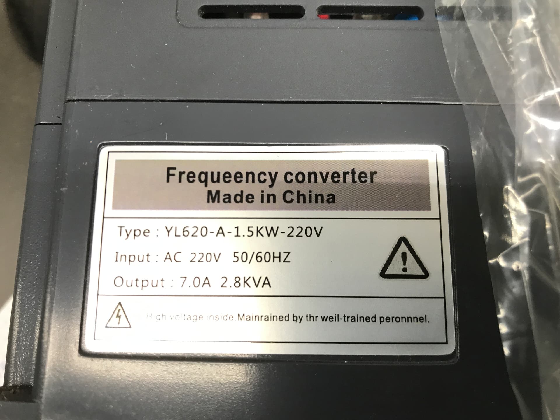
Thanks a lot! I will try located the rs485 pin in my VFD YL600.
…connect it to pin 13 and 14 on 25-pin I/O port on Breakout Board Adapter.


If you set the parameter P00.01 like described above, and the Serial Communications Settings P03.00 - P03.04, you should be able to “Run” and “Stop” the VFD on the touch screen of the Onefinity Controller.
But if you have a spindle connected to it, be sure to have configured the other parameters according to your spindle manual!
Also to control Spindle speed (=frequency) by the Onefinity Controller, you also have to set “Frequency Source Selection” to “(ModBus Rs485) Given frequency”.
Waooooo! Thanks a lot, I will verify all this information.
Muchas Gracias desde Puerto Rico!!!
¡No ha sido nada! I’m just about to see which functions are comparable in known VFDs. But I feel sorry if someone didn’t get their device to work. These chinese manuals are unfortunately not as easy to understand as that of my Omron MX2
Hey Luis,
did you get it to work?
I got my YL working on RS485 on my OF. I have the right config and how to wire it up to run the Spindle on GCode.
If you still need this just let me know, maybe my setup will also work for yours.
Hey rickyacruz,
If you post the information, I will save it thankfully for an entry in a future VFD FAQ.
As you can read above, as far as I read the manual, we know the correct settings and wiring, but we may have overseen something.
Yet we have no news from Luis whether it worked or not.
Good morning!!!
Yes, if you can shear the information that will be grate.
Thanks!
Luis A. Miranda
939-642-3950 | lamvpr@gmail.com

Hi guys this is my actual unit, please see the setting pasted on my vfd body, I switch from Gcode to VFD dial depends on what I cut. Mostly I do auto on regular products and run manual on prototype products.
I hope this helps.
Thing to note is that the stopping setting for the spindle rotation is “Coasting Stop” and it takes about 10seconds for the spindle to come to a complete stop so be careful to touch the bit. I put some safety visual and audible devices to prevent accident when using my CNC and I also run my Vacuum and water pump together when the spindle spins (I used the VFD A0 terminal to run my SSR) not the OF as the VFD has a higher Amp Capacity and the AO Terminal runs with the spindle rotation.
Another thing is to not forget to connect the ground to common (besides the A and B terminal of vfd rs485)
Let me know if it works for you.
Lastly, be cautious when using the Breakout Board Pin 1,2 (load 1 and Load2) or even the Terminal for PWM, as it’s capacity is limited to max 25MilliAmp only or even less so check your SSR or relays power draw before using one (most SSR draws about 8milliAmp) but checking will prevent damage to the Controller and RasberryPi.
Hey rickyacruz,
thank you for sharing your settings and your information on the YL620-A VFD!
Yes, I have already noticed that some people like to turn the “Speed” button while the spindle is running and the CNC machine is at work. Normally, if the execution of the “Run” and the “Frequency” (=“Speed”) Commands is left over to the CNC controller via the RS-485 / ModBus serial connection, turning the Potentiometer has no more effect. I understand when some people switch back and forth between the two settings they call “Manual” and “Auto” then.
|
But it’s laborious to switch between these two if you have to brachiate through one-line menus on a Seven-segment display using four nasty Membrane keyboard buttons | 
|


In that regard the VFD Omron MX2 aka Hitachi WJ200 is particularly advantageous here, since it offers the “Forced Terminal Block” function. If you assign this function to one of the Intelligent Input Terminals, you can connect a switch which enables you to always quickly toggle that you want to operate the “Run” and “Speed” from the Operator Front Panel, even though the VFD is set to receive the commands from CNC controller ![]() . Unfortunately simple VFDs such as the Huanyang or the YL620-A do not offer such a functionality. With these, in order to switch from “Manual” (Operator Front Panel) to “Auto” (CNC Controller), you have to laboriously change the parameter settings (that you glued onto your VFD as shown above).
. Unfortunately simple VFDs such as the Huanyang or the YL620-A do not offer such a functionality. With these, in order to switch from “Manual” (Operator Front Panel) to “Auto” (CNC Controller), you have to laboriously change the parameter settings (that you glued onto your VFD as shown above).
I see that you asserted “Decelerating Stop” to “Manual” Mode and “Coasting Stop” to “Auto” Mode. I assume that when using “Manual” you have the enclosure open and want the safety of a spindle stopping immediately, while on ”Auto” mode it is not important for you that the spindle keeps spinning after powering it off. This presumably also spares the bearings.
Do you have a Brake Resistor connected to the VFD? As far as I know, most VFDs emit an Error if you select “Decelerating Stop” and no Brake Resistor is connected. Usually I would always advise to set it to “Coasting Stop” for this reason, unless I know that someone purchased the braking resistor with the VFD and has conected it.


Also in order not to kill your spindle on its first use, it is very important to set the Mandatory Spindle Parameters according to your spindle’s manual, datasheet, or motor plate.

If you are always near the machine when it is working, like most hobbyists, you will be satisfied with visible and audible alarms. If you want more security, you can set up a safety circuit that causes the VFD to stop the spindle in the event of errors. I recently showed wiring diagrams for this. Sensors for cooling water temperature and flow can be connected to a safety relay as well as an external Emergency Stop Switch.
This is perfect. It is the job of the VFD to ensure that the spindle water cooling is on when the spindle is running and VFDs are made for this.
Hey David,
is the manual you show on the picture a manual that you own? Unfortunately, the YL620-A Manual available at buildbotics.com is obviously made using OCR with some errors. Your picture shows differences also. Would you mind to scan your printed manual (if possible using a flat-bed scanner)?
Hey Rick @rhoffart,
Hey @rickyacruz,
Hey David @Dustydave,
Hey Luis @Lamvpr,
please would you mind taking a picture of your VFD’s Identification Plate? I dont’ mean the plate with the “YL620-A” on it or the one with the warnings, I mean the plate with the Manufacturer and the Rated Parameters, usually on the back, the side or the bottom of the device. I thank you very much!

That is all labels on case
Hey David,
Hah! I suspected that. No manufacturer.
I don’t think Yuyong industry is the manufacturer of these devices. They once sold them, but apparently no longer at the moment. At least not individually.
Thank you very much, that’s very kind of you!
Are you sure you want all 32 pages. I don’t have scanner but could take photos like the two above.
I would be glad to sell you the paperwork and the unit for $50. In original packaging never used beyond trying unsuccessfully to set it up. I sure due to my lack of knowledge and patience.