Hi everyone,I’m running into a positioning issue in Carveco Maker and could use some guidance.What happens:
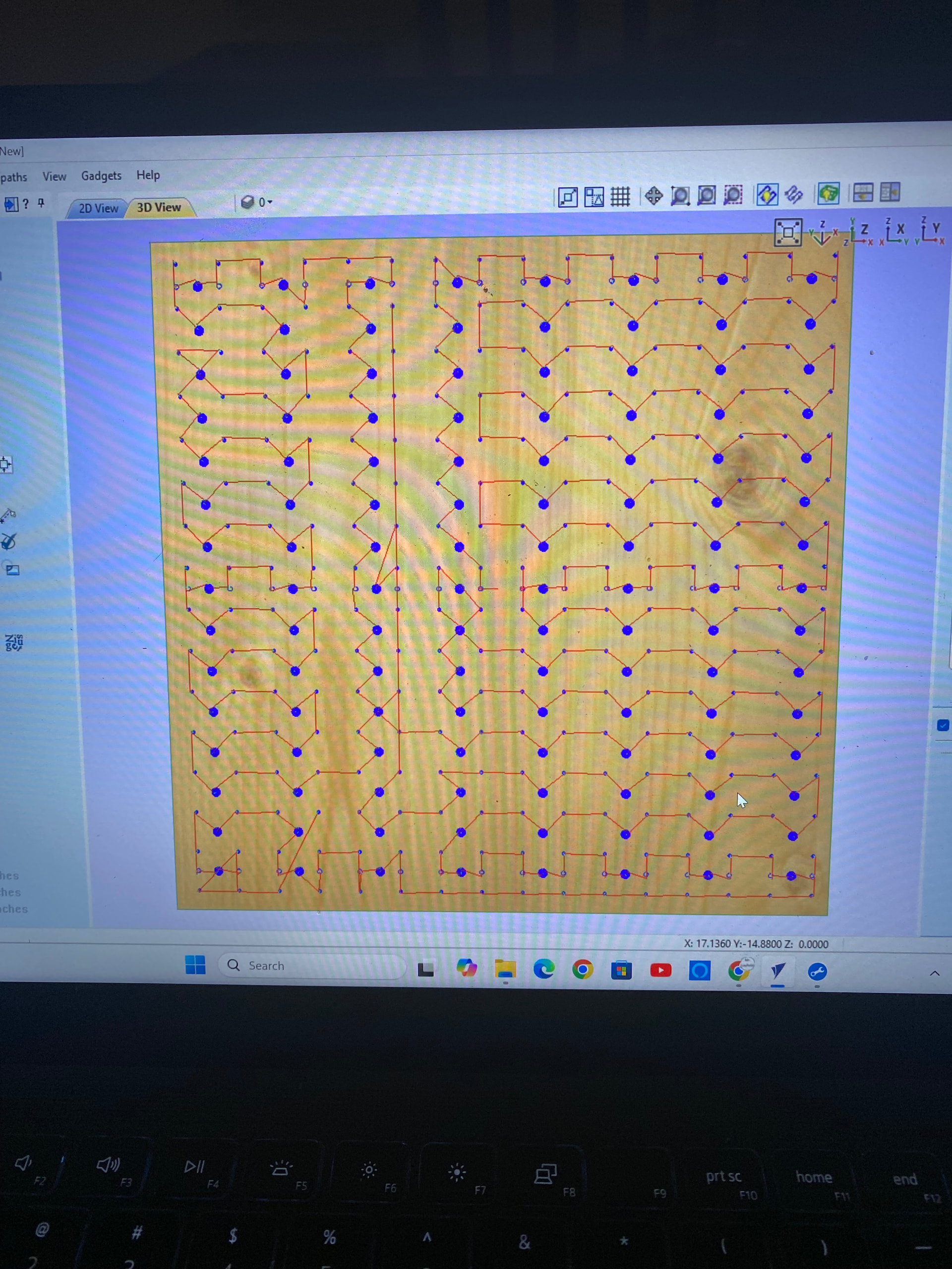
I import my 3D file (.stl/.obj/etc.) and open the relief.
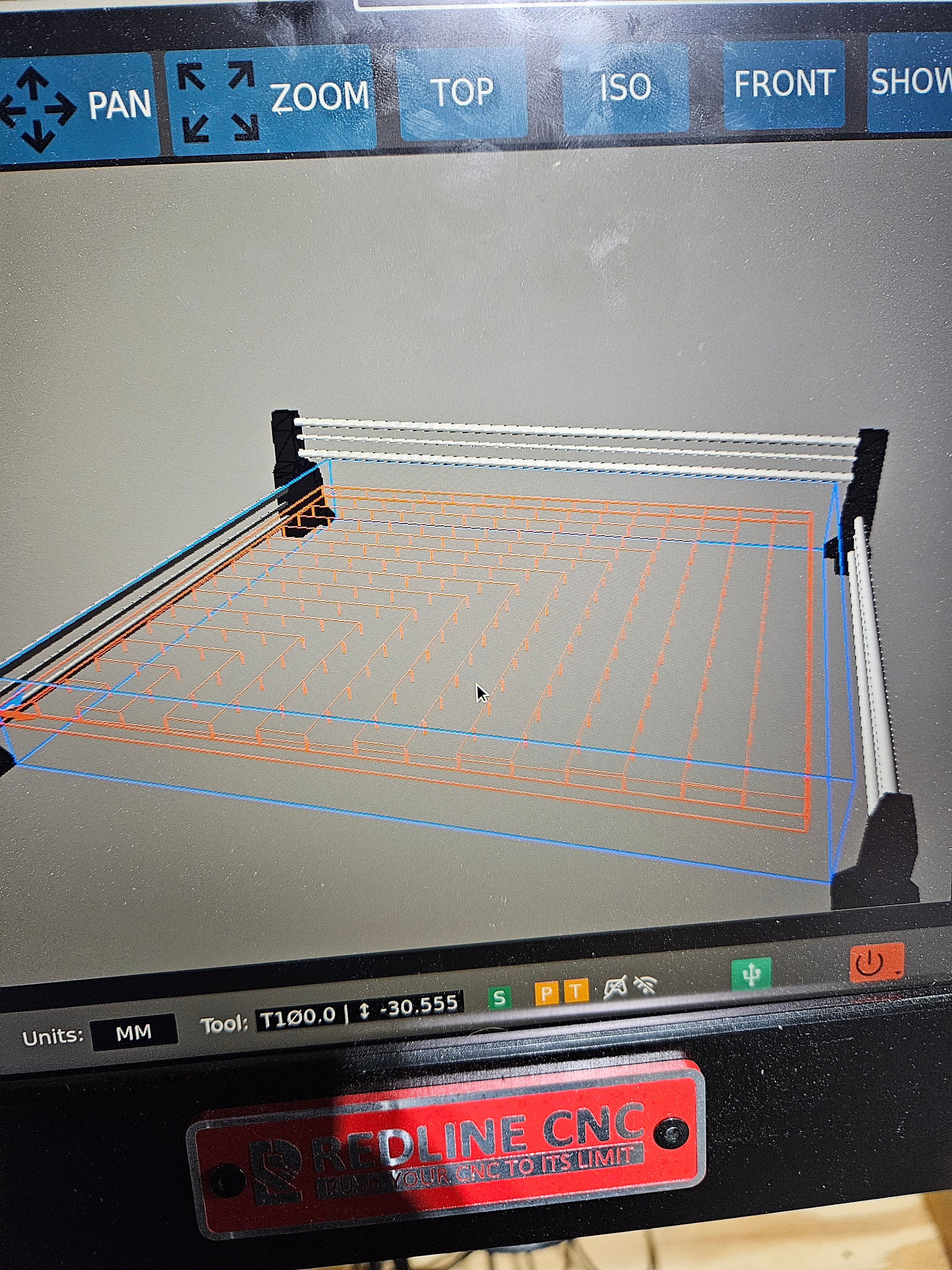
The model appears red in the 3D view, shifted 1 inch too far to the left.
When I try to post the toolpath and start the job, I get:
“Exceeded X travel by 1”
What I’ve tried:
I manually dragged the model to the right in Carveco Maker.
Recalculated toolpaths and re-exported G-code.
Result: Still red, same error on the machine.
Setup details:
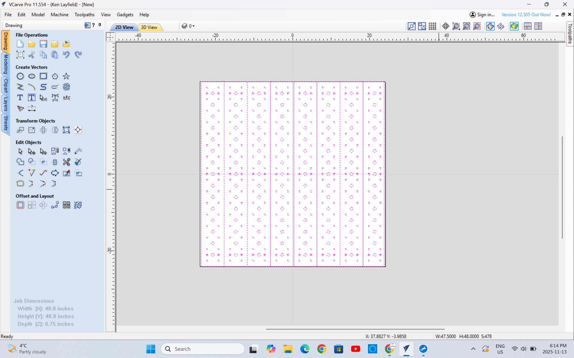
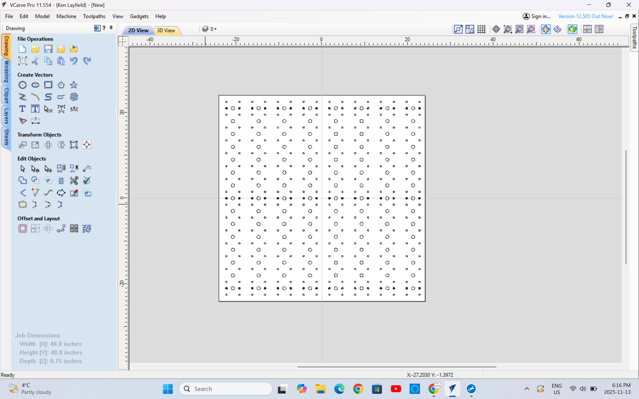
Material block is set up correctly (size matches stock).
Machine bed limits in Carveco match my CNC (X travel confirmed).
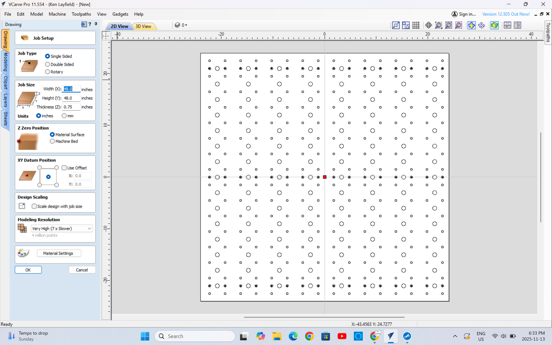
Job origin is set to center (tried lower-left too – no change).
Question:
How do I permanently shift the model 1 inch to the right so it fits within the machinable area, turns green, and allows the job to start without the X travel error?I suspect I’m not updating the actual job origin or toolpath bounds when I move it. Dragging clearly isn’t enough — what’s the correct workflow
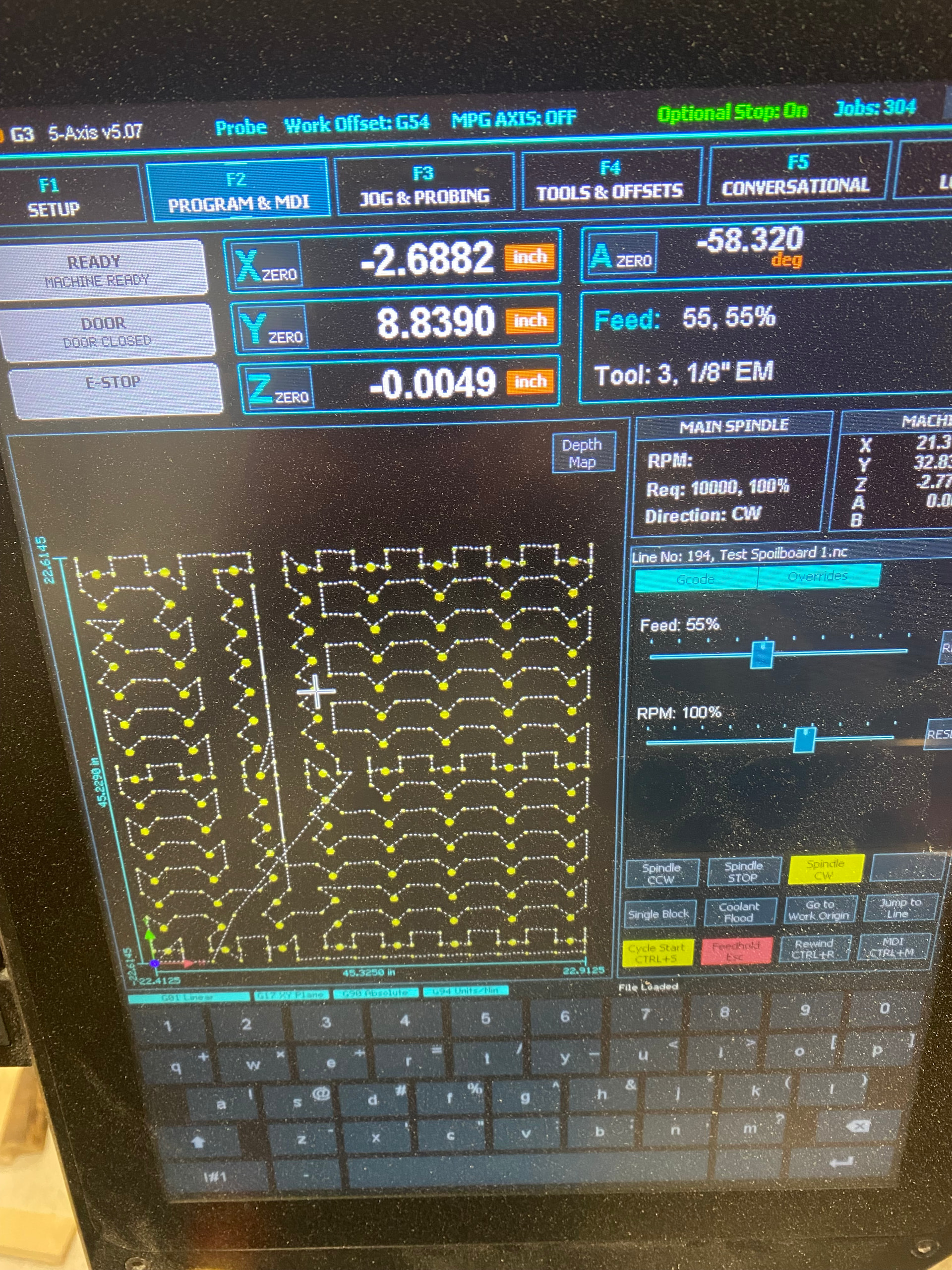
Is the tool being used for any of the edge objects wide enough that it will result in a cut outside the machine boundaries? For instance, when surfacing a board you can’t run a big cutter on the edges of the board because the diameter of the cutter head means it will cut outside the machine’s travel limits even though there is physical room for the cutter head to fit without whacking the rails. Something similar might be happening with those holes along the edges.
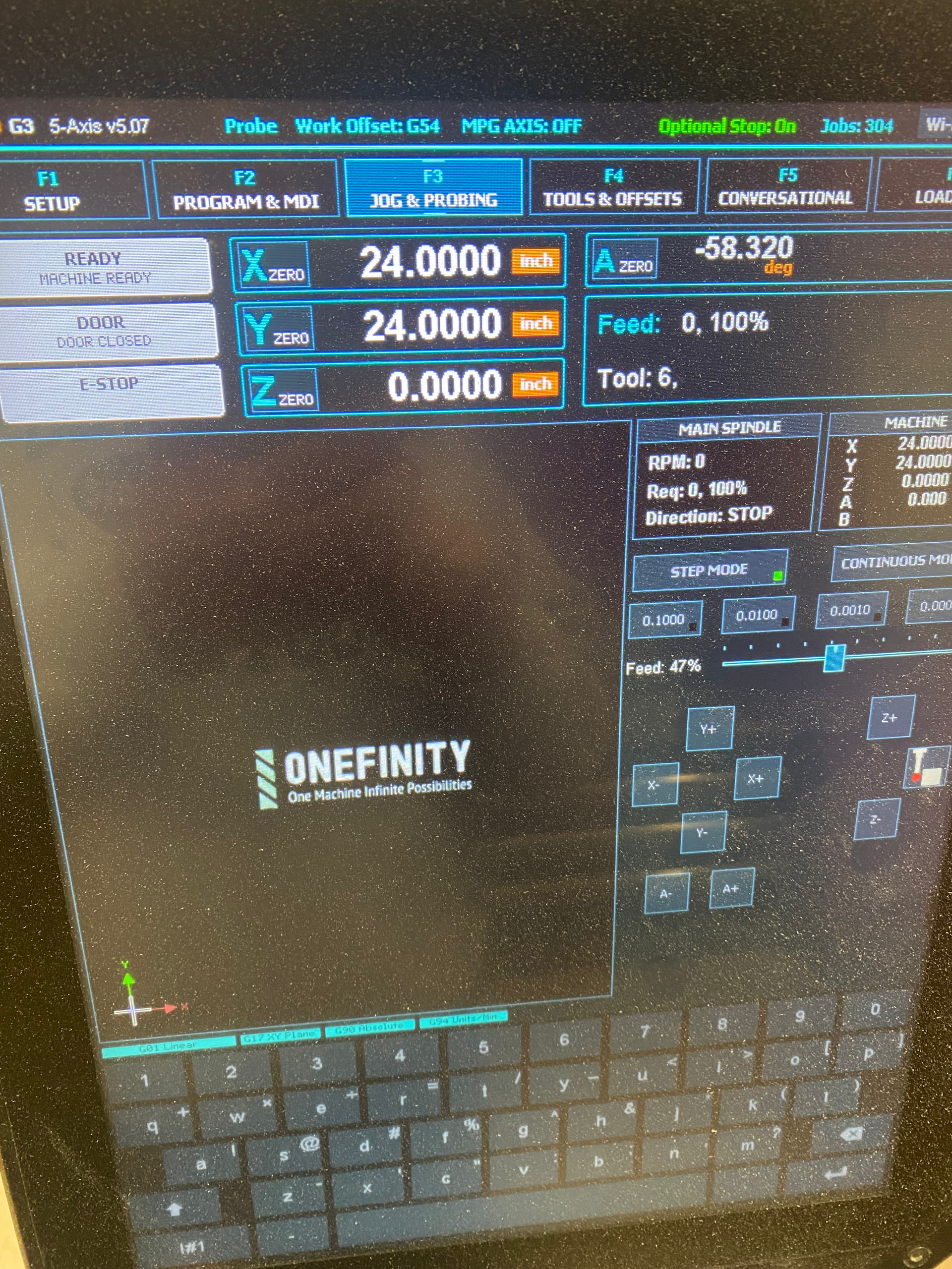
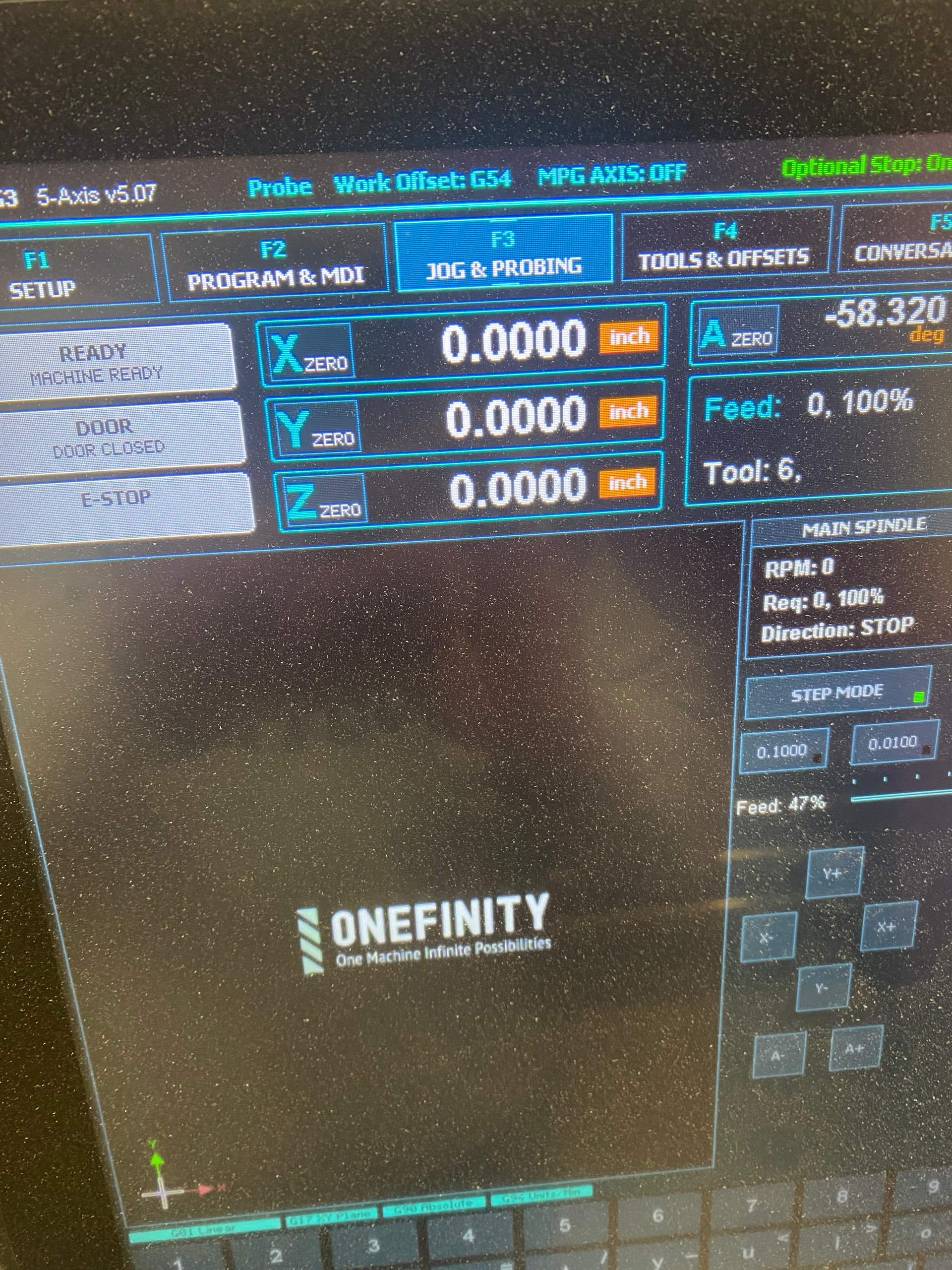
Also, after homing the machine and setting x & y zero, run the router all the way to the outside edge of the machine and check to see if that matches the file’s material size (or is larger) and the coordinates match the machine’s defined size in the config (& is as big as or larger than the project’s size).
Ken i tried it from the middle and yes it will run. Before I do anything I want @OnefinityCNC to tell me what i have to do to fix it. Do they still help people on this forum?
Have you tried their support email?
Over the last 20 odd years working with computers and cnc machines 90 % of the time the problem is located between the keyboard and the back of the seat