Just got mine all wired up 10k Ohm resister on the alarm and 2.2k Ohm resister on the enable. Is there anything else that needs to be done to enable the a-axis? I have gone in and activated the input on the setup screen, still nothing.
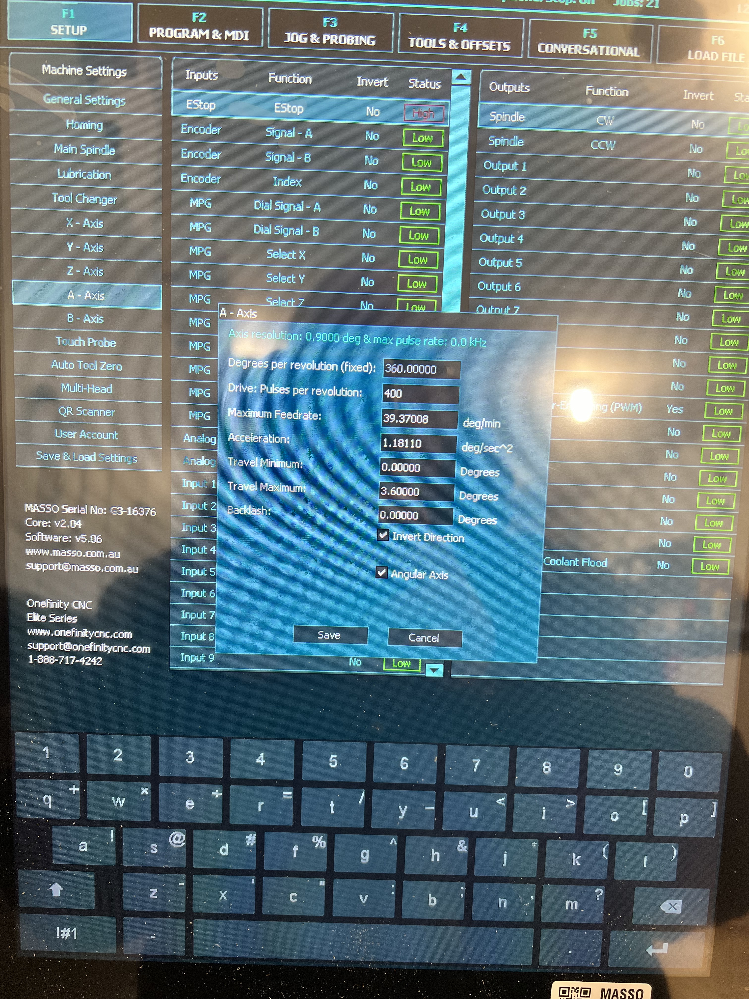
Try these as a test…
I do not use Masso motors, or have an Elite, so am not sure if your ENA and ALM are correct/working
Also, are you using it like a lathe or more like an indexer? That will influence the settings and they would/may differ from the screenshot example.
Yes it does get power (green light is on), but did not spin. I updated the Travel maximum to 60,000 and that got it going, will try upping it to -1000000 and 1000000.
Do you mind sharing your setting when you get a chance?
What are your switches set to to get the 4800 pulses per revolution? Mine are all on, so it is set to 400 per their data and how onefinity set them from the factory. When I use the 400 in the A Motor set up it doesn’t move. When I change it to 4800, like you, it works, but not correctly (is stretched). Is that value a calculation based on a calculation of the pulses per revolution (400) and something else (gear ratio, 6:1)? I am guessing it is a calculation since 4800 isn’t a value in their table for various switch settings.
I believe all motors are are supposed to be set to the same ppr, although, I’m not sure why Z and A would need to be the same. Did you already have your other motors at 800?
I actually had it at 9600 at first. I thought that was correct, but I noticed that with that setting, the machine was making two revolutions when it should only make one, so I cut it in half. I must not have initially accounted for 800 ppr on the motor.
I didn’t touch it when I removed it from the z axis (replaced with the brake motor), so it is still 400 like all the others. I will try 800 on all motors and update the F1 settings on all except A, leaving that at 4800.
Is that a 10 Ohm resister? It should be a 10,000 Ohm resister. It’s huge compared to what I have installed. Also, the resister on the enable wire should be 2,200 Ohm, not 2 Ohm.
I can’t see how your enable wire is connected from this picture.
EDIT: I think I can barely see the resister connecting into the terminal along with the dark green wire.
Your wiring seems correct except that the resisters may be the wrong ones.
You will specify the A axis alarm input in your setup. It doesn’t matter what one you use as long as it’s not used for something else.
I assume you booted up with everything connected. Did you notice what lights were on on the motor at that time, before doing anything? What did the lights look like when you pressed E Stop? Then, when you released it?
From what I could see in your pictures, it looked right except the 10/10k ohm resister issue. We couldn’t see the motor wiring, or the 2.2k ohm resister.
When I did mine, I took baby steps and checked everythign with a multimeter as I went along.