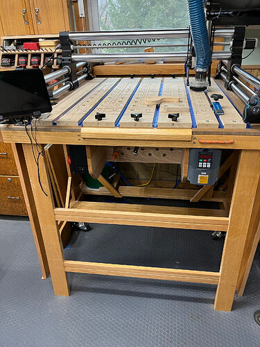
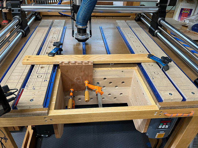
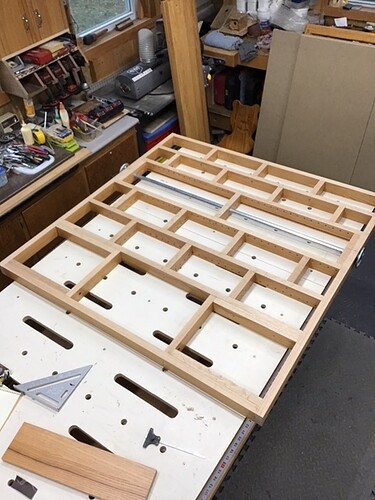
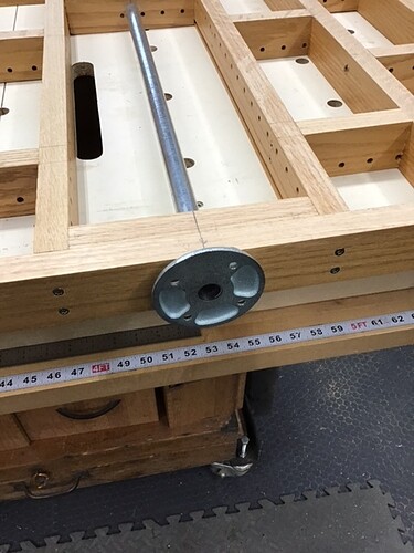
That’s why I built it for my JM. I had to modify his plans a bit as the JM needs a bigger table than the WW he designed it for. My overall length is 7’ long by 22" deep and 5’ tall when in tilt mode. The table top/torsion box is 4’ tall and 6’ wide when tilted. Here’s a pic. This is the underside of the table. Nice big flat workspace when not using the CNC. I added an electric winch (wireless fob control) because the 1F JM is very heavy and can get away from you when flipping it “closed”. It can be difficult to rotate back down by hand if the X-axis has slid to the front (I have spacer blocks I put in the rails to stop it from moving closer than about 14" from the front. You’re trying to tilt 150lbs of table top with a CG that’s towards the bottom of the tabletop. You’d need to lock the X axis into the center position parallel to the axle to have the CG balanced for tilting. The winch is a 12VDC Harbor Freight one and makes it a breeze to open or close regardless of where the X axis is.
My controller is in the cabinet where Drew has drawers. Putting it next to the 1F means it’s in the dust pathway and you’re always going to be messing with some electrical wiring when you open or close the table.
My drawer section is shallower than his (about 7") and oriented toward the end of the unit vs the front. The top section is a double-sized space with a flip down door that also locks into place horizontally when I open it. The controller and power setups are inside there mounted against the back of the cabinet section. This helps keep the wire connections out of the way and sawdust out of the controller. I’ve not had any heat issues but then it’s been cold - the door can stay open when I’m using it & with the “open up” style it will still keep the sawdust out while letting air flow in there if needed. Mounting it there has no impact on my wifi (mine works fine). It also allows running the X/Y/Z wires through the axle pipe and then inside the torsion box to come out below the motors.
This also means you don’t have to keep plugging them in & out when tilting the table for use. like Drew has his setup to do. The cable connectors really aren’t made to be plugged in/pulled out frequently. I only have to unplug my router power cable from the outlet on top of the cabinet when I want to tilt it.
The door is ajar in this pic but I have spring cabinet latches to hold it closed. BTW, the leg is attached here via a threaded rod into a threaded insert because I was waiting on my t-track and was impatient  The table now has the t-track mounting for the legs like Drew’s plans - they work better than just bolting the legs into the torsion box by keeping the legs snug when tilting so they don’t flop around.
For my JM I went with the 1F recommended 4’x6’ table top (torsion box). That’s actually a bit larger than necessary when putting the controller in the cabinet. I could have taken 6" off that and made my cabinet another 6" deeper or shortened the overall length. I’m not a big fan of deep drawers like Drew’s design has - things tend to get lost in the back/bottom. Shallow drawers work better for me and I think I have a couple more than he did in his plans. Each of my drawers contains just a few things that are grouped together. The top is the stuff I need to make it operational - dust shoe, some allen keys, touch probe, router wrenches, joypad, dust mask and safety glasses. The 2nd drawer are my end mills in a storage block I made that fits right in there that I can pull out and sit on top next to the Y-rail if I’m going to be using several bits for a project. It also has spare bits in their boxes as well as extra collets. The 3rd drawer has my blue tape, my double-sided carpet tape and my CA glue/accelerator. The 4th drawer has spare parts - extra joypad, mask filters, cleaning brushes & tool cleaner. The last drawer are the extra bits & pieces that come with the router but aren’t needed for the CNC as well as my spare brushes for the router. Because the drawers are shallow I can see all of the contents and I’m not jamming other stuff in there that would just end up being collected in the drawer vs belonging there.
I haven’t put in a drag chain. The motor wires go from the controller into the axle and then out the tee fitting in the first bay of the torsion box. The right Y-axis wire (I got the 4pk of extension wires from 1F) goes through holes I drilled into the torsion box webbing pieces to the front right corner where it comes out a hole right in front of the axis motor connector. The left Y-axis wire goes straight to the left front of the table and out through a hole in front of that motor. The X and Z wires come out in the center of the table (front to back) through a hole in the top that lets them get to the X/Z connectors. This way I only have the wire needed to travel half the length of the Y rail outside the box. A drag chain would seem to be more work for not a lot of benefit right now.
The Makita power is routed through a zip tie on the left X rail support and then runs to the power outlet on the top of the cabinet. It doesn’t have any issues reaching the whole table surface. The monitor power & HDMI wires drop down through the cabinet top into the cabinet to hook into the controller and into a power plug. The touch probe controller wire runs through the cabinet top as well. I unplug the probe box when putting it away and loop the probe’s wires around the monitor support. The monitor support turns so I can have it turned to face the front of the table in use and then rotated 90 degrees so it’s parallel when I flip the table.
This picture below shows how I’ve setup power and other connections.
As you can see, the back of the unit is where I bring power into it. There is a covered male outlet that I plug the female end of an extension cord into to bring power into the cabinet. The extension cord gets coiled up and stored under the table in the “bin” area when I put it away. I didn’t put the wire loop holders Drew made of walnut for his  In the top part of the cabinet, that power goes into a multi-outlet adapter for the controller, the monitor’s USB power plug and the surface mount power strip that’s mounted flush with the top of the cabinet. That power strip has 2 3-prong AC power outlets and two USB power outlets. The router goes in one of the AC outlets when it’s in use. I use the USB ones to recharge my earbuds and phone.
Also on top is a dual USB extension with a dust cover that runs into the cabinet and plugs into two of the USB ports on the controller. If I want to sneakernet files I can plug a thumb drive in and access the files. I could also plug in a wifi dongle but haven’t needed it because my wifi works fine. The extra port (dual vs single) was insurance in case I needed it.
I slide the hose through that and into the dust boot. It can be suspended from the ceiling via a spring hook setup I installed above where I usually use the table or just comes back to the front of the table and it slides along the project as needed. I have the Rowdy Roman boom components but that’s something I’d have to setup and take down every time I pull the table out or put it away. My hose management is working fine so far. It also has the advantage of allowing me to pull it out and easily reach around the table manually vacuuming up dust. The hose is coiled and stored in the bottom cubby alongside the extension cord. I’m using a ShopVac and a Dust Deputy setup - the DD saves a ton of filter replacements for the ShopVac.
Nothing yet here. I’m waiting on my QCW frame to put in a permanent wasteboard setup. Right now I have a 2x2x3/4 MDF piece, surfaced and then grooved with 2" markings & measurements. It’s scrwed down & countersunk. I can remove it or pop another couple of pieces of MDF on the table top if I’m doing a big piece that won’t fit on the 2x2 board I have there now.
I use the blue tape/CA hold down method or pin nails (23 ga pins) depending on what I’m doing. Mostly it’s blue tape. Pin nails are good because they’re very thin and won’t leave a big hole when you pop the material off and a carbide bit will just chew right through them without any problem. I have the VCarve file setup to create the holes for the QCW MDF panels but haven’t used it yet because I want to make sure they work against a real unit vs just the drawings provided by 1F. I’m supposed to get my QCW this month per the latest from 1F but if it’s delayed again I’ll probably just lay down some more MDF and t-track. The t-track will let me clamp as well as tape/glue or nail. I did a whole wasteboard setup with threaded inserts, etc for the Shopbot I was using for years but the other hold-down options are better for most use and when I need to have downward clamping force the t-tracks with clamps should be fine. I don’t see needing the threaded insert style with the way I work. You might want to try the other methods first and then see if it’s worth the trouble of putting in a couple of hundred threaded inserts 
3/4" 4x8 plywood is not. So you’ll need to clean up the edges & such of your table and cabinets with a flush trim router bit where the real dimensions will otherwise leave you with tiny overhangs. Also, if you want to run your power and your motor wires in the axle pipe you’ll want to go to 1" pipe. I was hesitant to put both through the axle due to the AC causing interference in the motor wires. Also, I would add another tee to the axle pipe on the right side so you can run the wire through that vs. drilling holes in all of the webbing pieces that are otherwise in the way. I couldn’t find the polypropylene connector he used as axle bushings at the big box stores so I used PVC couplers that I then had to open up a bit with a forstner bit (you could also use a 3/4" spindle sander) because the 1 1/4" PVC ID is just a touch smaller than the 3/4" black pipe OD. After I got it all assembled though I found the polypro connectors at my local hardware store. I bought a bunch for building other tilt tables because I’m going to do this with other shop machines. You can also go with real machine bushings but you’ll want to source them (I found some on Amazon I would have bought if my PVC coupler ones didn’t work) before you build so you can be sure they’ll fit the pipe you use for an axle. Last thing is I added more webbing elements in the table than Drew did. He just specs a half-dozen parallel ones like this:
I ended up adding another set spaced every foot perpendicular to these. I glued & screwed them to the top (& the original supports) and then nailed them from the ends through the original supports. That created a grid support system more in line with the torsion box concept (although ridiculously overbuilt using all of this 3/4" and 1 1/2" stock). A torsion box could well have been made with 1/4" or 1/2" stock throughout including the plywood tabletops and still been strong & flat enough - that’s the whole point of torsion box engineering. Drew over-engineered it and then I doubled-down on that 
Finally, I keep the hose & extension cord in the left side cubby on the bottom and some pieces of material and miscellaneous tools in the right side cubby. You can also see small plywood pads I’ve got under the legs. That lets me deal with different placements of the table in my garage (you can see one leg happens to be on top of an anti-fatigue mat on the right for this location) by just swapping out different pads. The pads allow me to swing the legs down and onto the pad and then I can kick the pad & leg into place. I don’t have to mess with leg leveling as a result. I have inscribed vertical lines on the table top ends so I can get the legs vertical without having to check for plumb. I made the pads and added the lines after I setup my table and got the top level front to back & side to side. As long as I always set it up in this direction I can put it anywhere in this bay and not need to worry about releveling. The rear legs (nearest the garage door) are actually adjusted a bit longer than the front legs to account for the slope of the floor to allow water to run out of the garage.
I’ve also added a couple of rectangular rare earth magnets to the cabinet side facing the front of the table. When I’m using it I put the router wrenches to the magnet and they’re handy but not put down somewhere that they’ll get in the way. Did the same for the joypad with another magnet on the back side - just make sure the polarity works before you glue them in place.
I intended to just use the monitor to control it but I’ve found I’m messing with the cut files in the garage vs. going back inside so I’m bringing my laptop into the garage. I am going to add a mount for a laptop arm & tray. I use one on my CNC plasma cutter and I’ll just swap it to the 1F when I’m doing router projects. It swivels on a pin hinge so it’s easy to move between machines. But that’s just my workflow. BTW, get yourself a stool if you don’t already have one. It’ll make babysitting jobs or working on design files easier on your feet.
All of the stuff here can be gotten either at HD or Amazon. I used HD for the structural stuff and Amazon for everything else. I can get you the links to the monitor stand, flush mount power strip, power inlet and USB ports if you want them.


