Hey David,
at the moment after roughly looking through this printed version of a manual I can say few things:
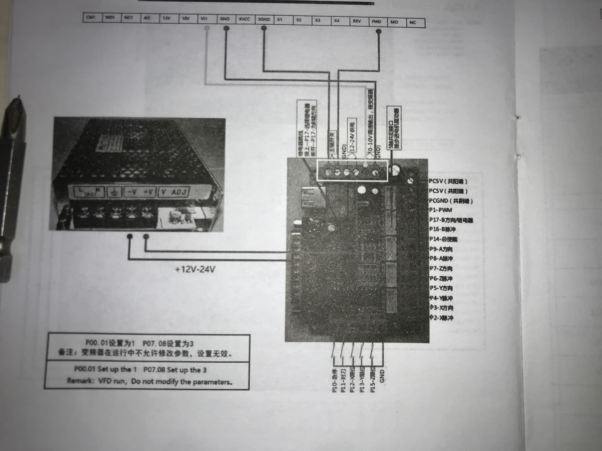
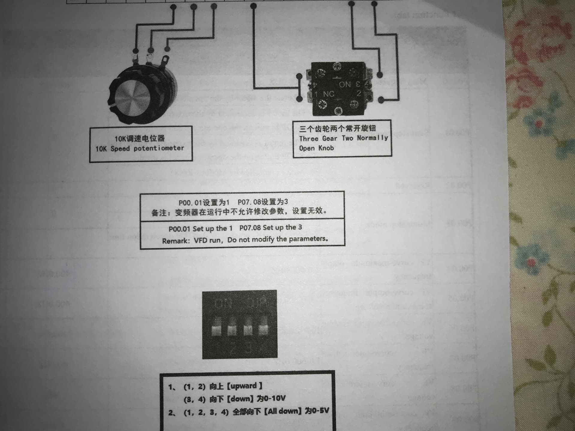
- On page 13 we have the 0-5 V / 0-10 V jumper explained which is not found neither in buildbotics.com nor in bulkman3d.com PDFs
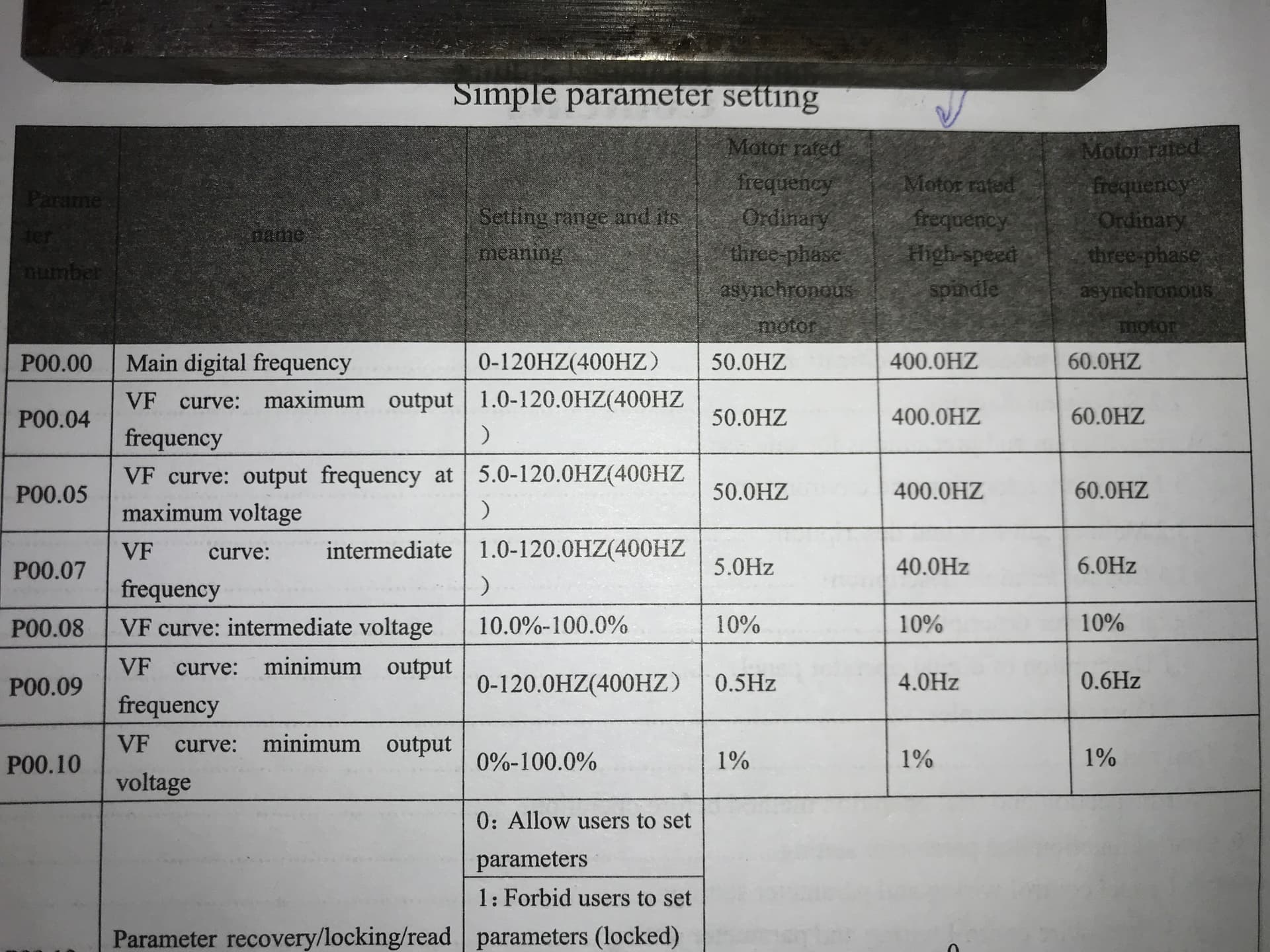
- Interesting is the table “Simple parameter setting” which is a sort of quick setup guide and which has three columns of possible user settings. This is missing in both PDFs mentioned above
- Unfortunately I can confirm again that in this manual, generally things are explained poorly or not at all and can only be understood by people with much experience with VFDs - and this applies to most manuals of cheap chinese VFDs.
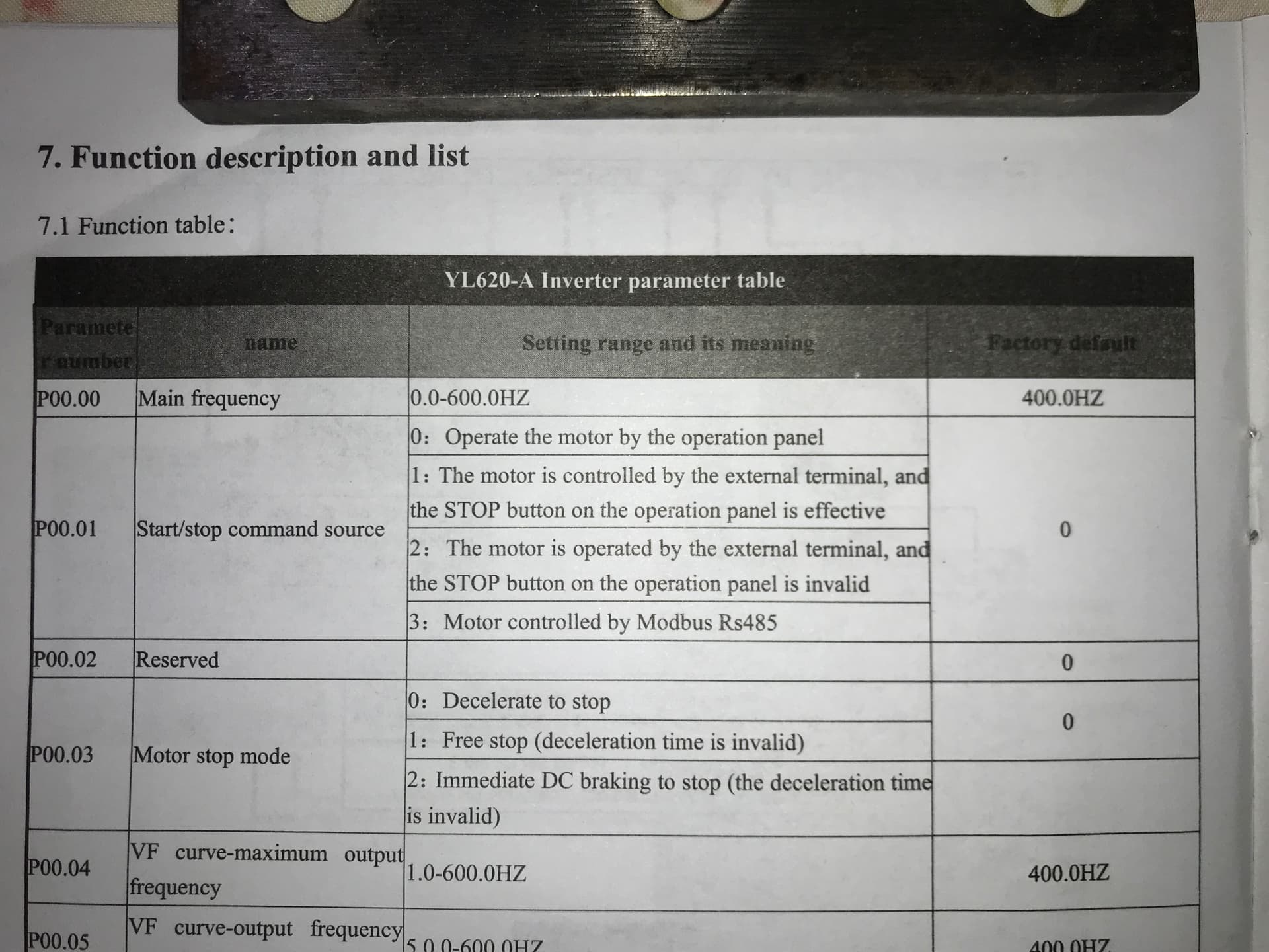
- But the usual capabilities are there, including V/F parameter settings, programmable digital and analog input terminals as well as output terminals and of course a user RS-485 ModBus Interface.
- Some things remain strange (as usual in these manuals for cheap chinese VFDs) and probably will have to be tried out.
David, you said once you tried to get it to run. What exactly did you try? Did you have a spindle wired to it? Or was it the Serial Connection to the Onefinity Controller that you tried out and was not working?
It was hooked to a spindle
I could use it by using the potentiometer
I wanted to connect to the controller and that was like hitting a brick wall, spoke with folks tried to talk with the vendor and just was not able to resolve
So I just cut my losses and purchased a different unit and it took about ten minutes to hook things up and it has been  no issues.
The only thing I miss is the fan did not run all the time and when it did it was short. The drone of the fan now does get to me sometimes
I have been able to slowly grow my work load and would like to be able to use 1/2” shank. So I am slowly working towards that goal.
I have ordered the 80 mm mount. My hung yang VFD is able to drive a 220 volt 2.2 kw spindle. So I am looking for a spindle. I would like to purchase a German spindle but can’t justify the cost delta. Still pondering that call.
1 Like
I have this same VFD. Does anyone know how to get it to display RPM rather than hz? Also am I to understand that I need to reverse the RS485 on the breakout board? So what I would think should go into 13 and 14 should be the opposite? Thanks.
You could try pressing the ‘Shift’ key … works on my Huanyang VFD.
1 Like
Different vfd but I couldn’t get mine to display rpm correctly (conversion issues). Leaving as Hz has not been a problem (rarely look at it). rpm is transmitted from the vfd to the controller for displaying alongside the expected rpm.
1 Like
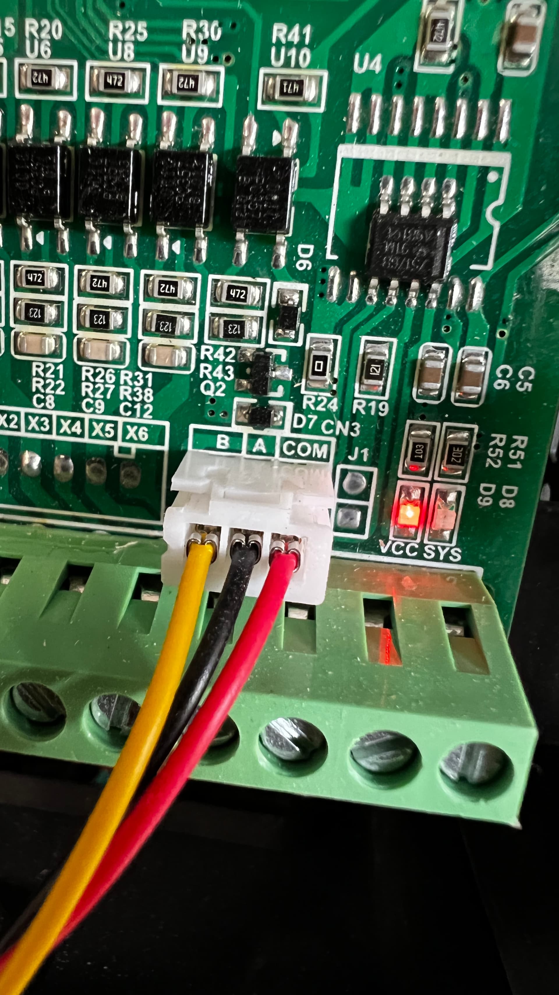
Shift key doesn’t work sadly. However I am trying to get it hooked up to the controller with the breakout board but I am having some roadblocks. @rickyacruz may i ask how you connected the RS486 bus to the breakout board? My VFD has a female JST Xh connector for the RS486 bus. Is there another way other than that? This my current RS486 output.
1 Like
Hey Lee,
you have two versions of the Manual in this thread.
-
As you can read here, CN4 CN8 are the pins for the ModBus Interface for communication to a PC or a standalone CNC Controller. Do you have pins with these names?
-
Also be sure to set P03.00, P03.01 and P03.02 to identical parameters as set in the CNC Controller. Especially address (P03.01) must be the same!
-
For display of speed instead of frequency after power-on try to set P00.24 to 6.
Do you have a printed manual?
Hi,
Im out of town for the holidays and I cant seem to find the photos I took of the BOB. I will send u as soon as I get back. But, Im think I connected the VFD “A” terminal on BOB T13 and the VFD “B” on BOB T14, and the VFD RS485 common on either BOB T19 or 25 (ground). I think this is the main difference with YL the grounding and the Coasting Stop setting.
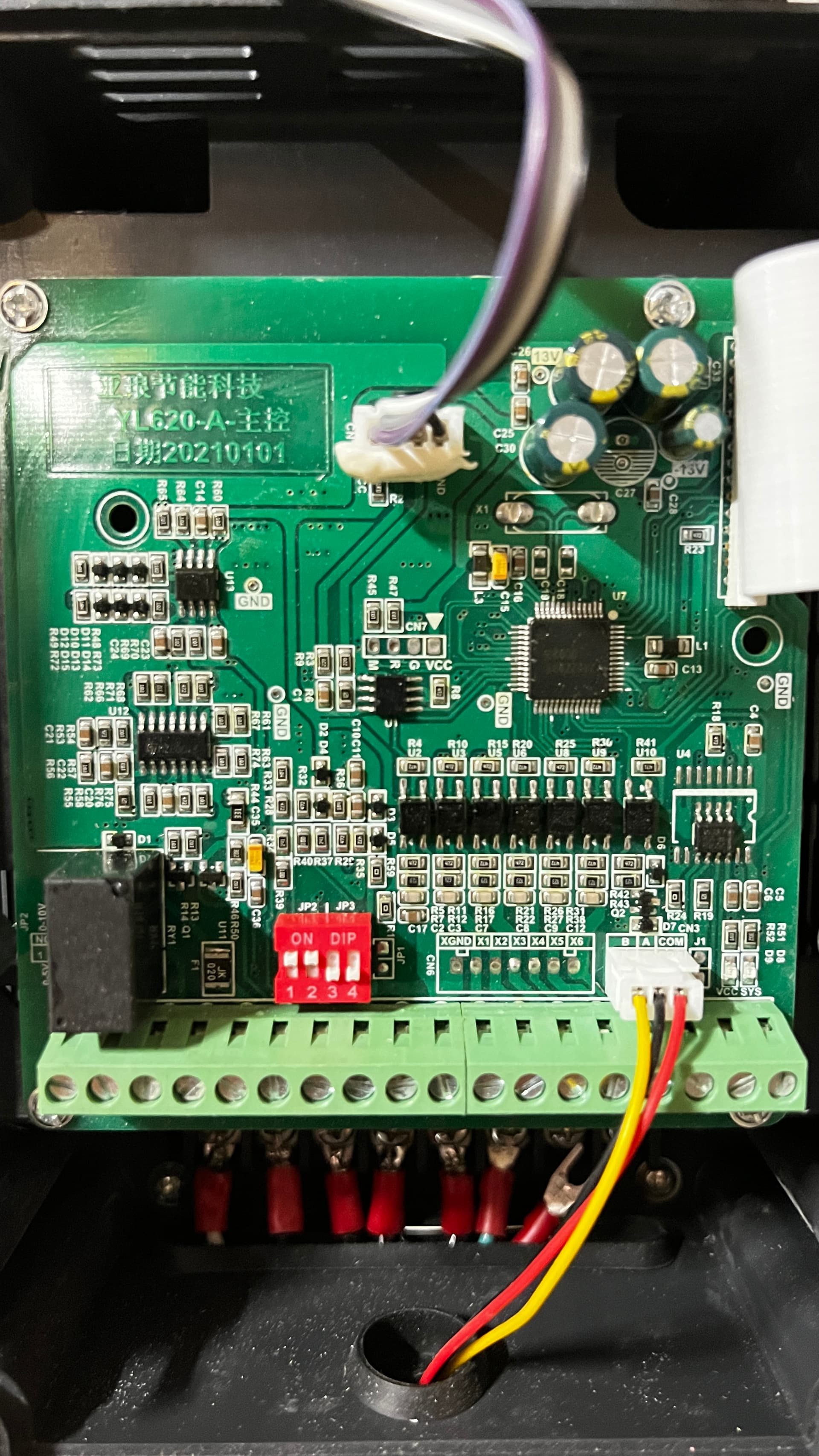
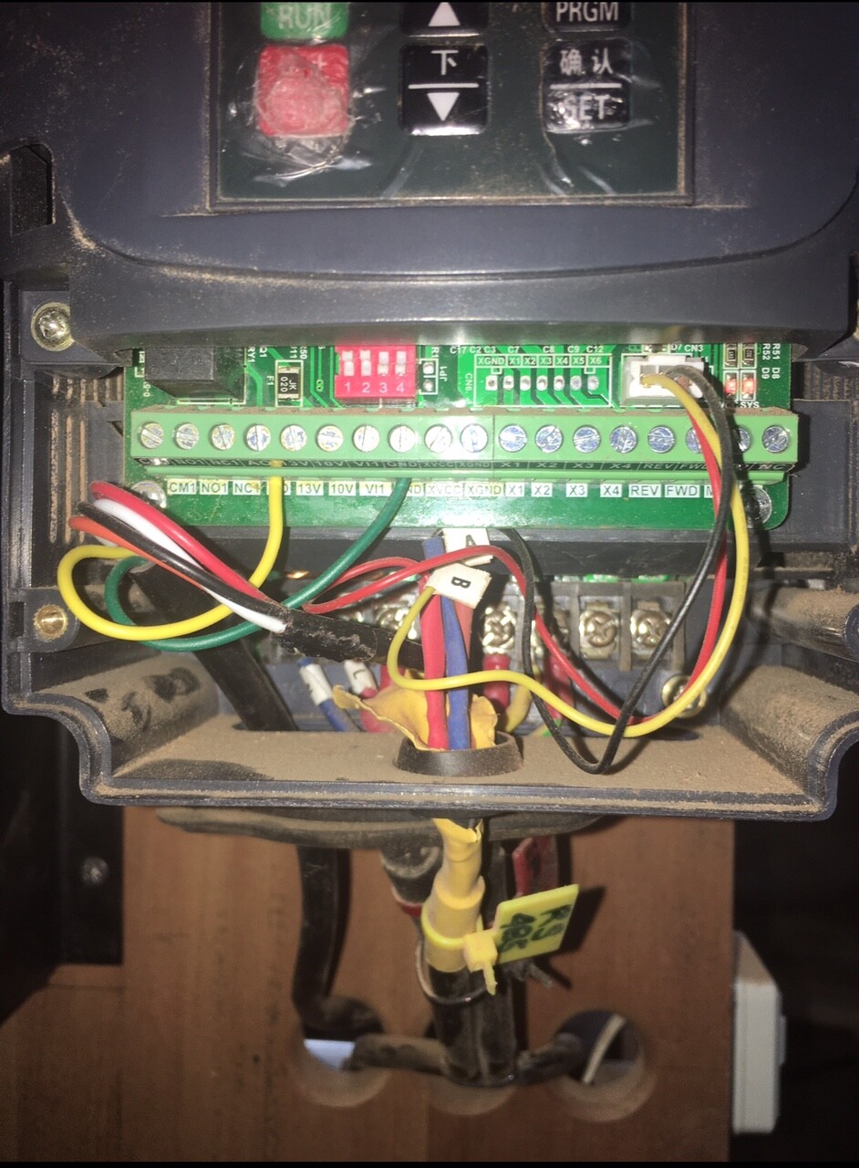
I never got a manual which made me a bit frustrated on top of having a Yuanwang Ali Express knock off . I have been looking through the photos of the manual and the pdf on the buildbotics website. I thought I had everything in order with my wiring and with the programming but it seems that I don’t. I did see the CN4 CN8 message above in this thread but I am not sure what that would correspond to on the VFD pcb board. I do see CN6, CN7, CN3 and CN1 (hidden by the cord at the top of the image).
Thanks @rickyacruz I appreciate your help. When you get back from out of town I would love to see your wiring for the RS485 bus on the VFD board, I thought I had it right but I guess not.
Did u see the photo of my setting on VFd? Thats all U need and this 3wires RS485 to Breakout board.
If u need anything best ti do via zoom or messenger
Hey Lee, hey rickyacruz, hey Dave, hey Dave, hey Andy,
Lee, thanks for the photo. Does the 3-wire cable on the lower right lead to the operator panel?
Many VFDs have two RS-485 ports. The first is for communication with the operator panel, and a second RS-485 port for communication with an external device like a computer or a cnc controller. According to the manual this VFD has such two ports, it’s in both versions here and here:


Your pcb corresponds to what is shown here and here, but it seems that the users there did not find a second RS-485 port either but unplugged the operator panel instead and connected their cable on its 3-pin port on the pcb. Of course this port might work too, but this port might not be configurable. According to manual, only the second RS-485 port is configurable by P03.00-P03.04. I don’t know whether @rickyacruz connected the cable to these pins too.
Unfortunately, with cheap chinese VFDs it is a common experience that they do not correspond to their “manual” or are subject to change without notice. So according to manual, I would look at two headers called “CN4” and “CN8” and I cannot provide more information as I do not own such a VFD. Maybe it is on the underside of the PCB? Or in a daughter pcb? Or maybe there is a RJ-45 connector in the side or the back of the case, or behind the Operator panel?
In case you can find no second RS-485 port, you could use the first one that is attached to the Operator Panel. It should be noted that on a RS-485 bus, multiple devices can be attached in parallel:
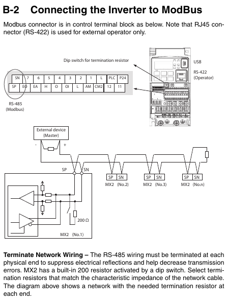
(Source: Omron MX2 User’s Manual)
The different devices are distinguished by their bus-id then. So if you don’t find any other RS-485 port, you could connect it
- in place of Operator Panel, or
- parallel to Operator Panel. In any case make sure the termination resistors are only a the ends.
In the manuals, the settings for the Operator Panel are 19200 Bd, 8N1, and bus-id=10, but this friendly user at forum.linuxcnc.org reports in fact that it’s 38400 Bd!
The Lower Right (Marked A/B/COM) is the RS485 so it goes to your OF BoB 13,14 and 19.
Theres no other terminal to connect if you are just interested in Gcode run of spindle, (provided you have set the OF config to run the spindle). The wires with purple white black must be the LED display/potentiometer but that will not anymore be needed (just for viewing the Freq) when u run on GCode. I have enclosed previously foto of my actual vfd with notes on what to change when running on Gcode and when running on LED/Potentiometer.
Hey rickyacruz,
ah okay, but does the lower right connector with yellow/black/red cable go to the Operator Panel??
Hey rickyacruz,
thanks for the photo!
Does the lower right connector with yellow/black/red cable go to the Operator Panel normally? and you connected the CNC Controller instead of Operator Panel? Or in parallel to Operator Panel?
those yellow black red wires goes to the OF breakout board 13,14,19 respectively.
And before anything else, I connected all my grounding wires on : OF, Spindle, VFD and Breakout board. You will also find that by doing this, you will not need the magnet wire for the OF Touch probe( I can show you how to rewire the touch probe to get rid of the magnet wire, its a simple wire switch)
Yes. I know. My question is: BEFORE you connected the Onefinity Controller to it, did the lower right connector with yellow/black/red cable go to the Operator Panel?
And is it still attached?
sorry its yellow 14, Black 13, red 19
Ah, okay. Good to know. Nice of you to share this information repeatedly.
But one question: BEFORE you connected the Onefinity Controller to it, did the lower right connector with yellow/black/red cable go to the Operator Panel?