That must have been a satisfying moment when the bolts went in - your set-up looks great. I am getting quotes for a metal base - not sure if I want steel or a thicker aluminum plate - did you find your base to be rigid even before bolting it on top of the aluminum extrusions? Also, I notice the DOCS controller - are you planning to use the OF controller or your own?
That whole thing looks stout as hell… Woodworker looks stiff… That looks crazy stiff
@TMToronto I actually only put 1 bolt in each corner temporarily, I just eyeballed the holes and everything looks to be kosher.
Yeah, on the controller… I was learning certain things about the controller I wouldn’t be happy with, so I decided to build my own. This is virtually identical to the one I built & used with my x-carve for 4 years, so I’m used to it.
Yeah, no doubt! I took off the 3rd rail to do some adjustments, and don’t really think I’ll put it back on, it’s serious overkill on the machinist. Plus the additional dead weight could dampen quick front-to-back directional change when running. And it just looks top-heavy with it on. I plan on doing some flex testing measurements with an indicator, and suspect this will also show that it’s unnecessary on the machinist.

May I ask what things in particular you found limiting or missing in the OF controller.
That looks great Bill, thanks for sharing the pictures. I have one thing to ask that will help me be prepared for mine. How long were the M5 bolts you used to mount it to your table and were they button head or cap screws. I’m finding M5’s can be expensive and don’t want to buy anything longer than necessary.
When I was looking more closely at the controller picture you posted I noticed a dimensioned drawing and black plates, and then on your OF it looked like there are plates under the four y axis mounts that raise it up about 1 cm from the metal base. Did you have these made and add them to get greater clearance for the x axis mount as it moves across the table? This clearance was one thing I wondered about on the OF as perhaps it would allow for debris to get jammed underneath during use.
There were a few things I’ve read, mostly pertaining to bit changes & not being able to jog after a program pause. I’m accustomed to full functionality & control after having used this controller for the past 4 years. Plus, all my existing programs will run on this controller.
@Laserlarry, Thanks Larry! I think it should work out great. I measured roughly 21.3mm from the top of the screw shoulder to my baseplate, but that was measuring also thru a 1/4" spacer I’m using, so that would make the shoulder to base dimension 15mm.
As of right now (for initial setup), I’ve just got a single pan-head M6 screw in the one location on each corner that isn’t going into the extrusion. After the dust settles, I think I’m going to need 30mm screws to get thru my steel baseplate & into the extrusion slots. I’d like to use the location I have tapped out to M6 to ultimately use a 5/16" short locating pin (I haven’t measured yet, but I think the mounting holes in the blocks are 8mm). Should have a better idea after I get done with the controller hookup and can focus more on the mounting. It’s looking like M5 cap screws will require a good size washer. Even a button head would benefit from a washer. Will report more later… just getting ready to head out to the shop.


Good job Bill, looks great!
Thanks Larry! Had a bit of a struggle with the wiring, but worked through it today.
Bill, did you find the dimensional drawings provided by OF to be accurate with respect to hole spacing of the aluminum mounts? If so, I would use the drawing they provided for the “Woodworker” to locate the holes for a metal base.
Thank you,
Tom
Hey Tom, yes, it definitely proved to be accurate enough. The Y axis block holes are 8mm, and my attachment hardware is 5mm, so there’s that. But the alignment seems very good. At the moment, I just have 1 bolt in each corner, as I was more focused on getting everything else put together & working. I will need to go back & finalize the mounting.
Thank you. It looks like there is also an expanded area at the top of the bolt holes. Is the through hole diameter 8mm, and room for a washer on top? if yes, would you know the diameter of this top circular area?
Thank you,
Tom
Just ran out & measured it: the c’bore diameter is 15mm, and the length of the 8mm hole is 15mm top to bottom.
Thank you so much for the information - I appreciate it. You must be excited to start creating work that maximizes the functionality of the OF. Maybe you will have time to show some of your finished work in the future.
You’re very welcome Tom, anytime! Yeah, I’m anxious to get going on it. It took all day, well, basically all weekend to sort out a wiring issue I had, but now that I’m done with that, I can focus on getting things aligned & calibrated. Will definitely share work, but mine tends to be more simplistic than a lot of the intricate 3D carvings I’ve seen pics of. But yes, definitely anxious to cut something with it!
Thanks Tom for the follow up question about the size of the countersink hole and thank you Bill for measuring everything for us. I definitely know what length I need to get now. Some of my table frame work is under some of the mounting holes so I didn’t want to go too long( I know I could cut them). Good luck today fine tuning everything.
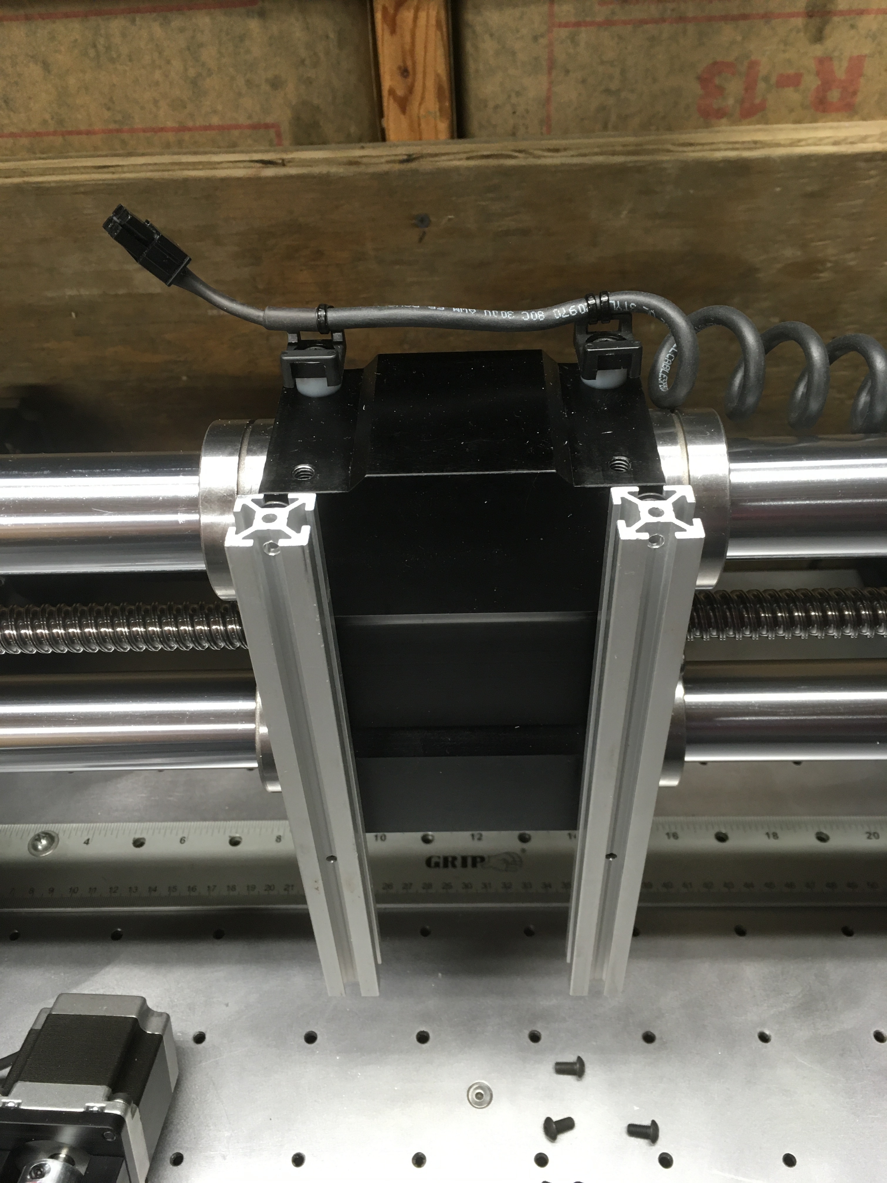
Thanks Larry, today’s project (well, probably today & tomorrow) will be to add some alum. extrusion rails between the bearing block & Z axis assembly to get the additional depth required by not having a wasteboard. Will supply pics if you’re interested. This won’t be an issue using your vise, but anything down close to the table surface (where I typically work) will require the extra reach down. This will be the cheap & easy way forward to get up & running, but I may revisit this in the future for a better solution. I don’t know… I’ll see how this works out first. May be no need for anything more elaborate.
Yes, I would like to see pictures of the extra rails. I wanted my machine mounted to the aluminum plate so it would be perfectly level side to side and front to back. I believe that will mean anything I surface will also be perfectly level. I’m planing on building up the work surface to the 2.5 to 3 inches high that is mentioned somewhere on the web site. Will the shortened z travel help, I’ll let you know. I have material on hand to do it so its a free experiment. The times I would not have any waste board would be , like you said, if I’m using the vice, if I’m cutting dovetails or if I’m cutting something really thick like a 4x4 post. But I still want to see your extension because maybe building it up isn’t the way to go.
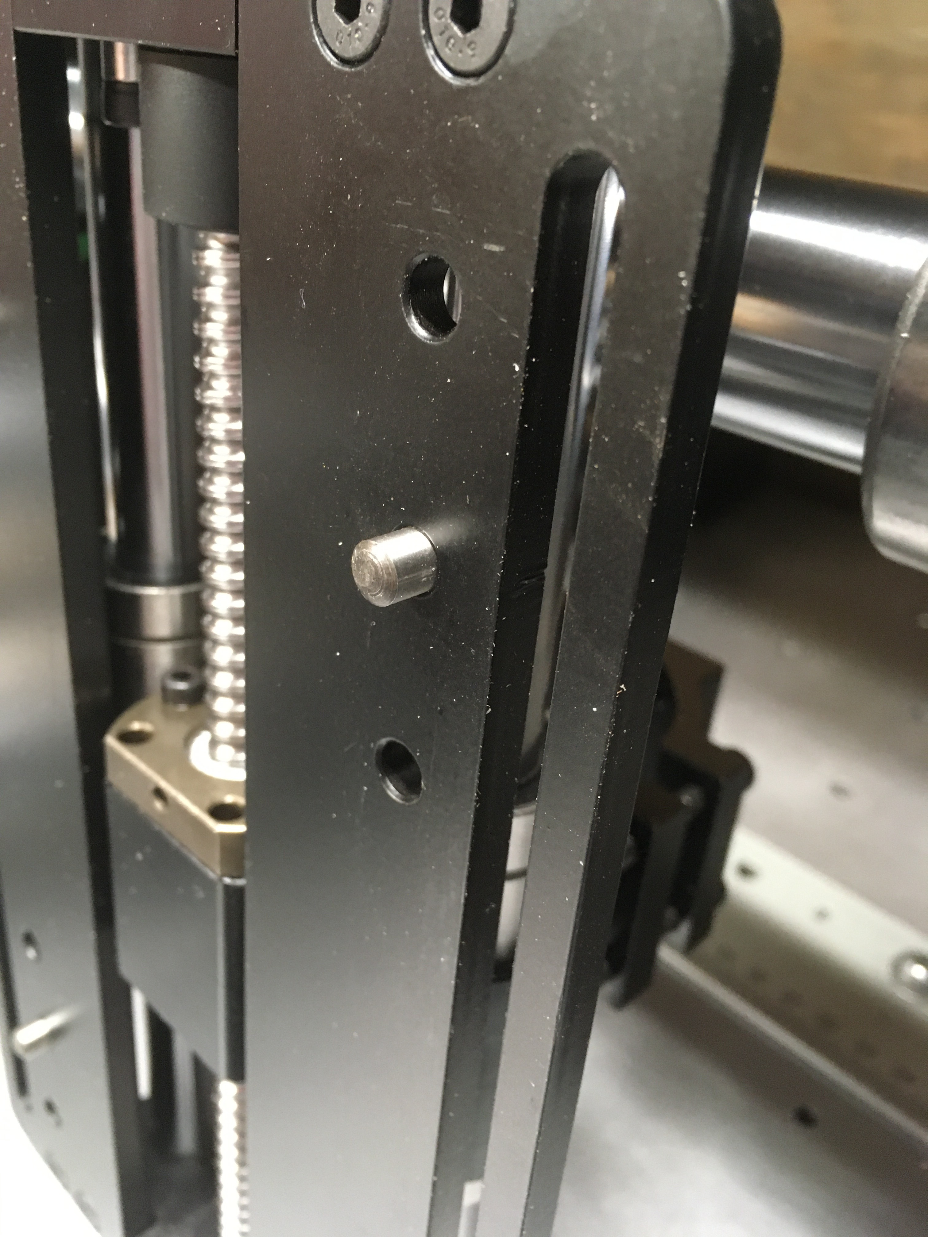
@Laserlarry, I did end up getting it completed this afternoon. I placed 6mm dowel pins in the middle hole positions of the Z axis that keep the assembly aligned by engaging the 6mm slots in the alum. extrusions. Not necessary, but very nice for keeping the Z axis aligned vertically. I used M5 flanged-head screws to attach the 20 x 20 extrusion pieces to the X axis bearing block, and then used screws in 8 locations (upper & lower hole positions) to attach the Z axis to the extrusions.
It would ultimately be better to mount the z axis in the center position, but that would require another smaller baseplate & frame assembly on top of my existing base. I may still opt to do this later, I don’t know. Note that this modification will complicate dust shoe mounting, but I don’t use one so it’s no big deal to me.