That’s really clever. The pictures you took do a great job of showing how you did it. I don’t have any of the aluminum extrusion but if raising my work surface up doesn’t work it won’t be hard to get some. I was reading another post about tramming the router, is that what you’ll be doing tomorrow? Good job, thanks for sharing .
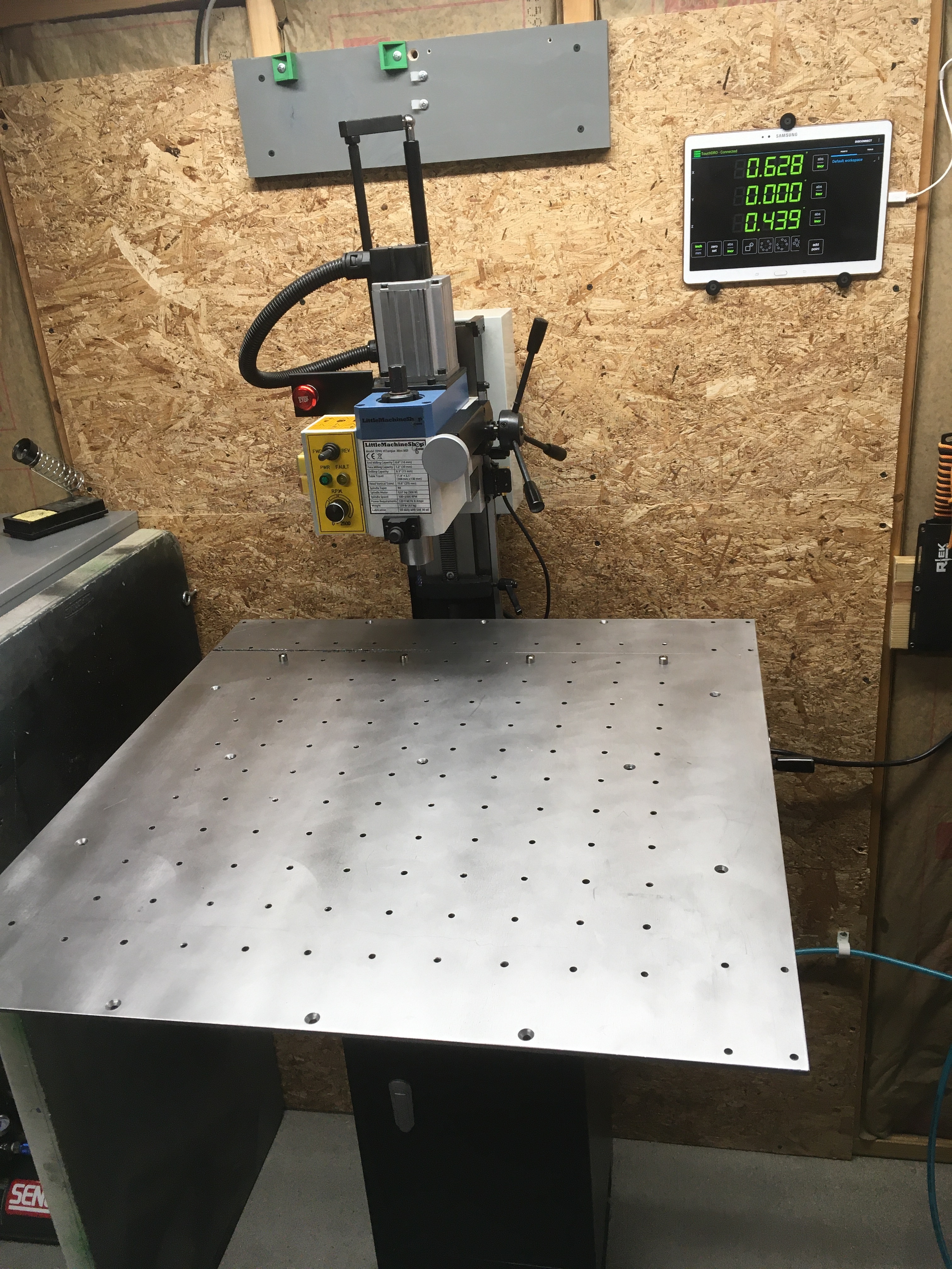
Since I squared the aluminum extrusions when I put them on, the z axis was/is essentially self-tramming thanks to the 6mm pins that engage the 6mm slots in the extrusion. I will double-check it though.
Raising your work surface is ultimately a better, more stable solution. While what I did seems pretty solid, it’s still a compromise solution. Keeping the Z axis assembly more vertically centered to the gantry is preferable.


I am joining your design part uninvited - so my apologies up front.
What if you kept your existing table as it is truly a solid well thought out base, and designed a smaller raised accessory base (much like the redesign that you posted) that could be bolted to the existing base when needed/wanted. You could place it on aluminum extrusions that would make use of the tapped holes you have, and the additional cost would be of a smaller metal base that would be bolted to the extrusions. It shouldn’t take too much time to add or remove it for the different project applications you have.
Welcome aboard Tom! Now I’m going to add my 2 cents. Bill as far as cutting the 4" inches off, I looked back and you said a vendor of your company made the plate for you,right? If they have a laser and large router I bet they also have a shear that could cut 7ga CRS. You are probably +/- .0625 on the finished size so it should be real easy, If you decide to do it. Tom’s idea is good. Correct me if I’m wrong but you both want to machine Aluminum and therefore are staying away from wood for a base, right? How consistent is the size of the extrusion over a long length? I’ve never worked with it so I don’t know. If it varies to much your work could be sitting crooked. Could you bolt the extrusion to the 7 ga plate and “surface it” with an end mill before attaching the second level? It’s a good idea to make the machine flexible when it comes to the thickness of the material you’ll be cutting. I’m interested in what you think about the surfacing idea.
PS Tom, I don’t know if you realize that I live just south of Niagara Falls NY. If only the border wasn’t closed
Hey Tom, you are absolutely invited, no apologies necessary!
What you suggested was actually my first thought. However, it was going to be cheaper/easier for me to modify my existing plate. Additionally, I like the new design better. My biggest hesitation was trying to figure out how to cut the 4" off each side of the plate, and then realized I could actually do it on my mini mill, in a 3" vise, no less! Time-consuming, but doable. Got the extrusion ordered as well.
I could probably have had the vendor that made it in the first place do it for me, but that would be extra time & $$, and wouldn’t be able to have it done until after the first of the year. This way, I should be able to have the steel plate done tomorrow.

Larry, the alum. extrusion is actually very straight, and especially so in the relatively short lengths I’m using. The stackup between the steel plate & alum. extrusion is extremely accurate, so no need in surfacing it (it would probably not even be as good after the fact). Any slight inaccuracy could be handled with shimming, but I don’t think that will be necessary. Anyway, it’s underway now!
Ok Bill, keep the pictures coming.It’s interesting to see your drawing come to life.
Not much to show, other than the modified (narrowed 4" each side) baseplate. That was a HUGE undertaking on the mini mill! I honestly didn’t feel like doing the corner chamfers by the time I was done with the sides & c’sinking the 8 holes. The surface finish wasn’t the greatest due to fighting vibrations when cutting the plate. The finished edge off the mill resembled a very good quality plasma cut more so than a machined edge, but with the help of a large file & rotary tool sanding drum, it came out pretty decent. At least good enough to pass the demands of my OCD, lol.


Looks good Bill. Definitely weighs less then my aluminum plate but just as solid.
Thanks @Laserlarry I managed to get it reassembled today. Gotta say, I am liking the new setup. My Z axis is mounted on the middle set of holes, which is the sweet spot.


would you mind sending me the DXF file for your machinist?
thanks
Jeff
email at controlsystems@pldi.net
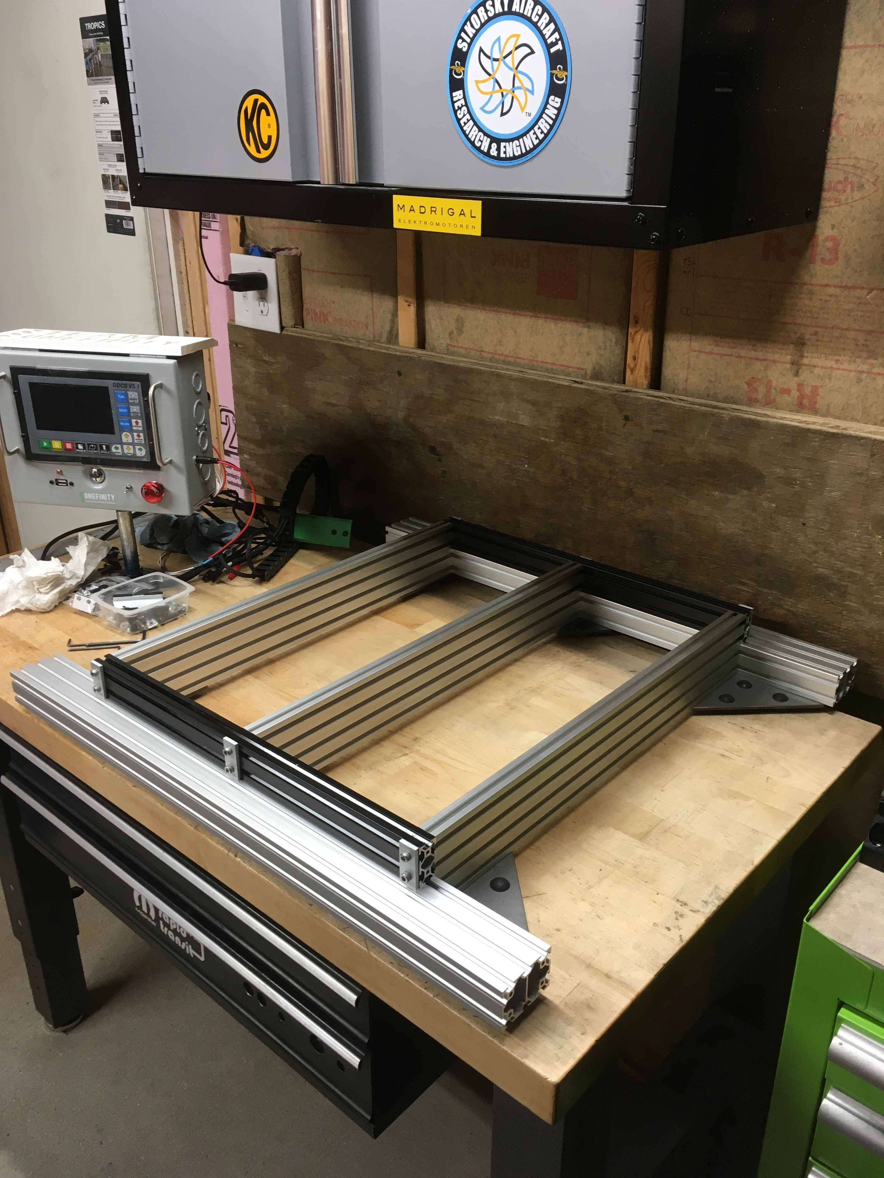
Here’s the baseplate DXF. The extrusions are as follows:
40mm x 60mm x 712mm (2 pcs.)
20mm x 80mm x 550mm (3 pcs.)
20mm x 40mm x 477mm (2 pcs.)
OFBP.dxf (126.7 KB)
Thanks this will be helpful
Jeff Ellis
Controls Engineer
Control Systems
580-305-4359
Additional hardware:
2-hole joining plates: 2 Hole Joining Strip Plate - OpenBuilds Part Store
M5 assembly nuts: Tee Nuts - M5 (10 Pack) - OpenBuilds Part Store
(you might find a 50-pack on Amazon, I think I’ve bought these before from there)
M5 x 20mm flanged socket cap screws (for securing Y axis blocks to the frame: McMaster-Carr
M5 x 8mm flanged socket cap screws: McMaster-Carr
M5 x 40mm socket head cap screws (no link)
M5 x 10mm flat head socket cap screws (for securing the steel plate to the frame)
Additional detail:
The 2 top holes are tapped in the 20 x 80 x 550 extrusion pieces. The 20 x 40 x 477 extrusions are drilled 5mm so they can be bolted to the 20 x 80 extrusions as shown.
The 20 x 40 x 477 extrusions are attached to the 40 x 60 x 550 extrusions (centrally located) by using the m5 x 8mm flanged socket cap screws, which nicely engage the lower slot in the 20 x 40 extrusion. There are 5mm allen wrench access holes drilled thru the top of the 20 x 40 extrusions in 4 places. This part is pretty tricky. See pic below for how this works. It’s not the exact application, but you get the idea of how it holds the frame extrusion in place. I would also recommend ‘trapping’ the t-nuts in place per the pic below. Otherwise, you’re in for a fight to keep things lined up while you tighten the screws. Securing the 20 x 40 extrusions to the 40 x 60 extrusions is actually an optional procedure, as everything will be sandwiched together by the upper work plate & lower angle plates.
I don’t have a DXF for the lower corner plates. They’re just 5" x 5" laser cut plates with holes for the rubber isolators. Unfortunately I don’t have a link for the rubber isolators, I got them from where I work, used on some of our products. I’m sure you’ll be able to find something equivelant that will probably screw on.


Excellent! Looks great Larry!
If you dont mind sending me he DXF file. Much appreciated
It’s posted in this thread, up a few posts from here.