Good day, everyone.
I was wondering if there are any hobbyist solutions for automatic tool changing available for onefinity? I have some large scale jobs that require multiple different tool paths and it’s also one of those bulk jobs where I need to mill 50 or so wood carvings for a staircase.
Hey Miles,
I don’t know what exactly would be the price margin to see it as available for hobbyists (in rich countries hobbyists buy expensive “toys”). These STC Series Automatic Tool Change Adapters can be retrofit to a non-ATC spindle. It’s not under $1000 but they are far under the price for the Professional ATC Spindles of the same manufacturer (STC Promo video, More videos: mechatron+stc+youtube.com). They may fit spindles from other manufacturers but one should be aware that with the Onefinity 65 mm mount, the the spindle will not clear the stepper so it won’t manage the extra length. With the optional 80 mm spindle mount , the spindle clears the stepper so you don’t have this limitation, but usually these spindle/STC units do have two mounts. I have no idea whether the single mount of the Onefinity will be enough to hold it. Maybe one could mount a second 80 mm spindle mount on top of the other, but you loose Z travel length then.
Besides this manufacturer, I have seen that here some other Automatic Tool Changers are offered but I don’t know anyhing about them
Quite a while ago a 1F owner shared his modified setup on Facebook - Maxwell Noah Kirsner.
If I recall he used the Mechatron ATC adapter @CommunityUser5 mentioned above, but he custom mounted it and the spindle to a RoverCNC Z axis mount, and I think he did use two brackets given the height of the combined spindle/ATC. He however also switched out his controller to a Masso Touch, which allowed him to fully automate the process. I have a Masso G3, and the controller makes the configuration and set up of the ATC very easy. When I can afford it, I plan to add an ATC spindle - I have been looking at the offerings of Jianken Electric Motor Company. It is a fair expense and level of commitment as it also involves the cost of the pneumatics and the associated electronics to get it to work.
Hey Tom,
(Btw, sad that people today don’t appreciate WWW anymore and use closed platforms.)
I did a quick search an had a look at this manufacturer. Looks heavy. And nice.
As I’ve stated earlier, and as one might guess based on my answer above, I see the Z Slider as the weakest part of the Onefinity CNC. After choosing the Onefinity, I thought a lot about how I would implement the ATC needed for serious throughput (Adapter like mentioned above, or ATC spindle), and kept thinking that the whole Z Slider could be swapped out.
PS: After X-50 has been released (and having ordered it), I am more confident that it will be strong enough for such a replacement Z Slider.
PS2:
Please, could you just show a screenshot of it? Of how it’s mounted on the X gantry?This is all I found publicly, it’s not a Onefinity: https://www.facebook.com/photo/?fbid=10215213621789645&set=a.2461441891190
Not on a onefinity but this is intriguing : PMATC Rev 2 - Cheap DIY Automatic Tool Change concept for non-ATC Router spindles -- Poor Man's ATC - YouTube
Hey BJ,
Cool (or do we say ‘sick’ today?), but I would say the DIY effort is overkill.
I think I too plan to upgrade to the X50 - would love to know how 1F determined its increased rigidity over the 35mm tube (theoretical or based on test data?). I am also looking asthe possibility of designing a new Z slider. My biggest concern is keeping the mass as close to the rails as possible. I had earlier looked at the RoverCNC setup, and if memory serves, it would have extended the spindle centre out perhaps 1-2cm further than the current 80mm mount. I wonder if the 1F team read/considered forum suggestions of selling a ‘universal’ mounting plate for those who plan to add other types of Z axis sliders/brackets.
Hey Tom,
TMToronto:
Quite a while ago a 1F owner shared his modified setup on Facebook […]
(Btw, sad that people today don’t appreciate WWW anymore and use closed platforms.)
but he custom mounted it and the spindle to a RoverCNC Z axis mount
I did a quick search an had a look at this manufacturer. Looks heavy. And nice.
As I’ve stated earlier, and as one might guess based on my answer above, I see the Z Slider as the weakest part of the Onefinity CNC. After choosing the Onefinity, I thought a lot about how I would implement the ATC needed for serious throughput (Adapter like mentioned above, or ATC spindle), and kept thinking that the whole Z Slider could be swapped out.
PS: After X-50 has been released (and having ordered it), I am more confident that it will be strong enough for such a replacement Z Slider.
I have these thoughts too, but in fact that’s what the Onefinity Creator did. It allowed him create a very light Z Slider with small rails. But it’s exaggeratedly light. And first of all, the spindle mount has only one linear bearing per side and has practically no vertical height. That’s the reason why there is no big plate for spindle mounts, the leverage force would be too high.
As far as I can imagine, when building your own, keeping the mass as close to the rails (and also as close to the X Rails I would suggest) as possible would require to exactly know and measure the parts one wants to use. I find that pretty demanding, you would need to buy hardware in advance just to estimate its possible use.
Usually Z Slider kits don’t seem to worry that much on keeping a small distance between the mass and the rails:
https://www.sorotec.de/shop/DIY-Kit-Z-Axis-Alu-Line.html
https://www.youtube.com/results?search_query=Sorotec+DIY-Kit+Z-Axis
PS: I think that the considerations made in this older thread have become more up-to-date with the advent of the X-50 rails. I believe that on Onefinity CNC, the torsion of the X rail pair is also something to consider because leverage force not only puts load on Z bearings but adds on X rails too, and new X-50 rails seem quite impressing now.
What I imagined among other things is: What if there were two 80 mm mounts, one on top of the other (thereby four linear bearings instead of two for the Z slider), but the Z rails would need to be much longer in order to retain Z travel length, but for the rest, leaving the Z Slider design as it is? This way the uniquely small distance between the milling motor mass and the rails would be retained.
I did look again this morning but can’t find his posts anywhere. He had sold his entire setup, and he started a company making their own CNCs. If I remember he milled an adapter plate to mount the RoverCNC unit to the 1F Z axis assembly.
We had similar thoughts. I was also impressed with how the 1F Z assembly design keeps the cutting centre close to the X axis rails. With the new X50 rails, I do not think adding a new (better/more flexible?) Z axis system that pushes the centre out 1-2cm more would be as much of a concern. I also consider buying and using a second 80mm mount. Right now the linear bearings being used are 70mm long, and the 80mm mount is 51mm high. If four new linear bearings are purchased that are 50mm long, then the overall double mount would be 102mm. The minimum amount of Z travel we would then loose would be 102mm - 70mm or ~ 30mm.
Hey Tom,
I agree.
I was about to order one, too. But then I thought, I’ll wait first how it looks the way it is.
It is good to have these measurements. I’m still waiting for my machine so I can not measure this.
I did not think of shorter bearings, that’s a good idea. 30 mm loss of Z travel is really not much, but we would only loose so little if the two 80 mm mounts would touch each other. I imagined the two bearings were further apart so that the leverage is really well distributed. See other Z Sliders. The further apart they were, the more weight you could put on them. Also if I would want to use the retrofit ATC Adapter for my existing spindle instead of a new ATC spindle (I’m not decided yet), I would say that such an ATC Adapter requires a second attachment, but a bit higher. In both cases, you would really need longer Z rails, otherwise you lose a lot of Z travel length.
But in any case, the shorter bearing would be something I’d like to try out (in the future when I’m ready). Do you have a source for it?
I did a quick search, and bearings of different lengths came up, but I did not specifically try to source a bearing of ~50mm length - I am sure we can get close to that from places like Misumi. I think that if you went with the ATC adapter, you would as you mention need the mounting brackets apart, and therefore need a completely different Z axis slider mechanism.
It looks like it would be easy to cross-thread the collet nut with that setup. But apparently it works so I guess not.
Something like this would be nice but no idea what it cost.
")
Hey Bob,
looks like normal ISO30 machine taper like available here. You need compressed air like shown in this video.
Since in your video on the spindle it says “RATTM” it should be rather cheap since rattmotor is a cheap chinese “brand”. Not like expensive ones.
I was using as an example of another method of making tool changes, no interest in the brand of tooling or the spindle.
I am currently buying the components and building all systems for my new ATC spindle. Going in to it I knew it would not be inexpensive, and not surprisingly…it is not (-:
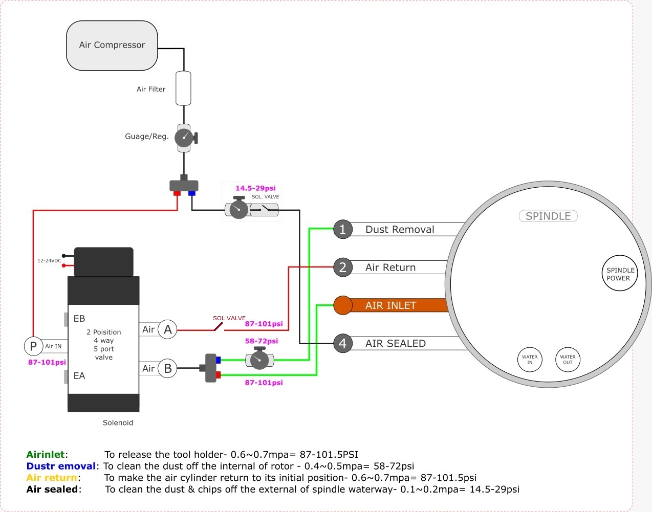
The image I included is from my spindle manufacturer, and shows the recommended pneumatics for running it. The costs of pressure regulators, micron filters, tubing, fittings, valves, power supply, etc adds up fast, and can be extreme if choosing products from established companies like Festo for example.
Tooling costs add up as well. I am going to be sourcing a variety of tool holders on both extremes of the cost spectrum, then evaluating their fit and finish, concentricity, etc once I eventually have things set up for milling.
What air compressor did you choose? Specs?
I don’t think I’ll add a tool changer, but I added an air seal to a Mechatron spindle after harm from brass dust. Mechatron sold me a Festo filter and solenoid, and the range of costs for compressors confuses me. The requirements seem to be 3.5 cfm at 4-6 bar, but sustained for long CNC projects. So the compressor has to either tolerate prolonged running or have sufficient tank space to allow 30/70 “on/resting” time.
Some folks say filter life can be reasonable if the air from the compressor is cleaner and drier than you get from a “big box store” compressor, but others say don’t worry about it ($300). Pros buy compressors at $8k and more. The advice that seemed most balanced (to me) were from Tractor Supply: a DeWalt 175284399 (60 gal, $800) or Ingersoll 3496129 ($1400).
What is the purpose for the solenoid between the filter and the spindle?
Do you wire it to turn on whenever your spindle runs, or do you use a separate switch?
I was sorry to hear about your spindle damage.
I run my CNC and related equipment in the basement of my small semi-detatched home, so noise and space are factors. Cost was also a factor in my initial choice of compressors. I have a 10 gal compressor that really is not suited to run my ATC system, but it was what I am currently willing to spend. It runs and barely keeps up with the air seal I use, so it is a compromise. I am considering experimenting with options to add either an auxillary tank, a second small compressor (which I have), or both.
The solenoid allows me to have the air seal on only when the spindle runs - I programmed an output from my VFD for this.
Hey Tom, hey David @Arzt, hey all,
interesting that on the image, they write the Megapascals as “mpa”, which would mean Millipascals, correct would be “MPa” for Megapascals ![]() And China is a country that is used to SI units – however obviously not that much to latin letter sysem
And China is a country that is used to SI units – however obviously not that much to latin letter sysem ![]()
Anyway, what matters here is that 1 bar = 0.1 MPa.
What I found sad on the most pneumatics documentation, e.g. on ATC spindle, is that they tell the needed pressure (bar, Pa, N/m², imperial: psi, lbf/in²), but not the needed air flow (m³/s, l/min, imperial: cfm), so it’s difficult to dimensionate the compressor with the spindle documentation alone.
Not Onefinity but this dude built an interesting project:
