Hello
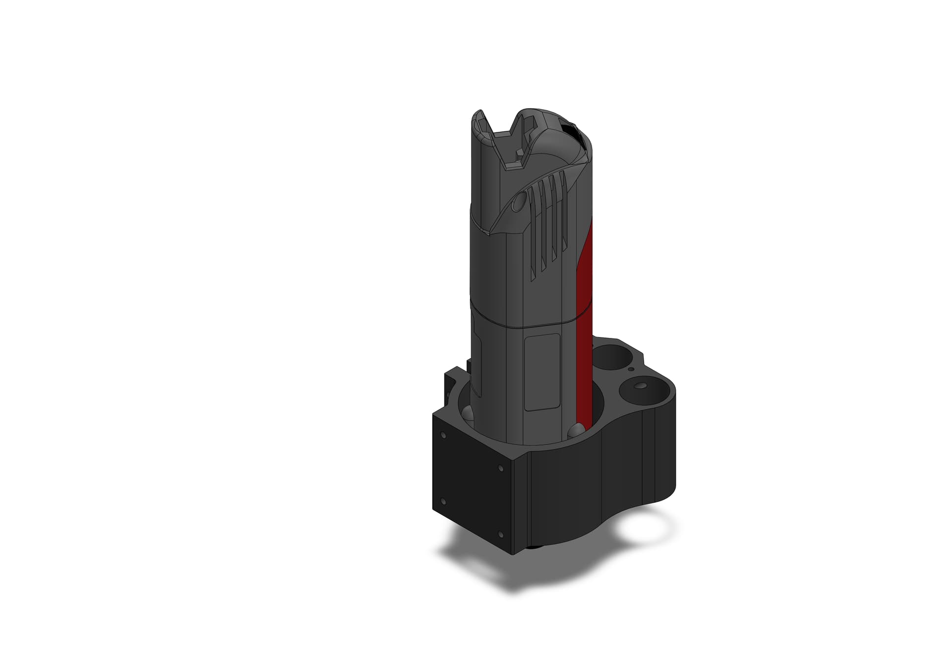
Have anyone tried this approach to mounting an 43mm spindle, AMD/Kress etc? It’s essentially just a colletring with ID=43mm and OD=80, clamped in the Onefinity 80mm mount.
Terje


3 Likes
Hey Terje,
yes, some of us have expressed both the need for it, as well as the plan to implement it (if someone can find the time), see here:
I personally think it’s a big mistake on Onefinity’s part not to offer an optional 43 mm mount, because with such an “Euro” mount, one would not only have a variety of milling motors as AMB (former Kress), Suhner, Mafell, etc. to choose from, but also a drilling machine with reduction gears (for drilling holes at very low speeds).
These are very nice pictures you created! Do you also have the capability to mill this in aluminium? ![]() Or a lathe to turn it?
Or a lathe to turn it?
If not, one idea I had was that one could buy this 43 mm mount and file off the overhang until it is 80 mm in diameter so that it fits into Onefinity’s mount. It’s already 80 × 80 mm in size!
5 Likes
Ahh, the lovely Kress type spindle shows up again! BTW, nice modeling @Temo! This could be easily machined out of Corian, which is suitable in a compressive application like this, but many other materials would be suitable as well.
The only potential issue I can see is that the distance from the nose of the collet to the bottom of the Onefinity spindle holder is pretty close, and won’t reach down to the work at the bottom of the Z travel. This would result in virtually no usable Z travel. By contrast, a router or spindle drops thru the holder quite a distance so will reach the work surface.

1 Like
Hey Bill, hey Terje,
but the other day we discussed that the need to slide the router or a 65 mm spindle that much downwards in the mount, with the result that the distance from bit to mount becomes “5″ish” as you called it (=12.7-cm-ish ![]() ), because otherwise the milling motor’s back would bump the Z stepper cage, is a strong disadvantage in matters of rigidity and chatterproofness.
), because otherwise the milling motor’s back would bump the Z stepper cage, is a strong disadvantage in matters of rigidity and chatterproofness.
But you are right, the opposite, I mean zero distance, would be a loss of Z travel. But that is due to the design of the Onefinity milling motor mount. It differs much from the usual spindle mounting plates (see links below) in that it does not protrude downward beyond the Z-rails end. Not at all. It leaves it up to the milling motor to protrude the Z assembly downward, and that is a severe disadvantage that costs Z travel if you want the collet to be close to the milling motor mount for matters of rigidity.
Usually gantry-type CNC machines are made so that the spindle mount is attached to a moving mounting plate that is able to protrude much below the Z assembly:
In this image you can see that this way a zero distance between milling motor clamp and motor axle output is implemented.
You can see a video of a moving spindle mounting cage here (shows Sorotec Alu-Line Z Assembly)
On Onefinity, the distance from mount to collet with a 80 mm spindle that people use is seen here and here.
@Temo I think that if you mill or turn such an adaptor ring I would use the full height of the Euro neck.
Generally I think the problem is the Onefinity Z assembly itself (and this is not the first time I think this way). Anyway I think that a one-piece, dedicated 43 mm mount, machined and offered by Onefinity, would be a better solution than an adaptor ring inside the 80 mm mount.
But I think for myself when the time comes I will see if I simply replace the Z assembly. There are many offered and Onefinity’s rectangular X gantry block should make it easy to attach one.
You can see many third-party Z axis assemblies here:
2 Likes
Thanks everyone, I guess it wasn’t that easy if the spindle does not reach down.
One would seriously have to butcher the 1F 80 mm mount to get this to work, and it would probably be to weak, but would be fun then!


2 Likes
I like this design, clean and simple. But I think the potential weakness may come from pushing the centerline of the spindle out yet farther from the support of the linear bearings. The dimensions shown here are just rough estimates based on scaling @Temo 's CAD view. I can’t find the actual dimensions now that were referenced in an earlier thread, but I believe the Onefinity 80mm spindle holder places the spindle centerline about 15mm out farther than the 65mm “standard” holder. This spindle would be approx. 41mm farther out from the current 65mm spindle (router) centerline.

EDIT: To clarify, I’m not saying that the 41mm offset distance is “too much”. Because looking at the 3D iso view of the design, it appears perfectly adequate and reasonable. If I’m being honest, it looks quite beefy in fact. The fact is that the Kress (or similar) spindle is far superior to a router, but how much will the 41mm offset difference play into the trade-off?
2 Likes
Hey Bill,
1 Like
Ha! I knew you’d come through! ![]()
1 Like
Hey Bill,
just coincidence that I saw your posting just when you posted it ![]() . I also have to leave right now (until later).
. I also have to leave right now (until later).
What I do is just eagerly use the bookmarks functionality of the forum ![]() With the amount of knowledge that can be found in the forum, I highly recommend it
With the amount of knowledge that can be found in the forum, I highly recommend it
1 Like
Going the other direction here is an 89mm 3d printed bracket I’ve been putting through its paces. 1/2” collet, 2.25hp and actually quieter than ye olde makita and no VFD. It is pushed out from the linear rails to clear the Z stepper and for sure rigidity takes a hit but I’ve been making some deep passes in hard maple and so far ok. 1F if you go start making alternative brackets add to the list?!

3 Likes
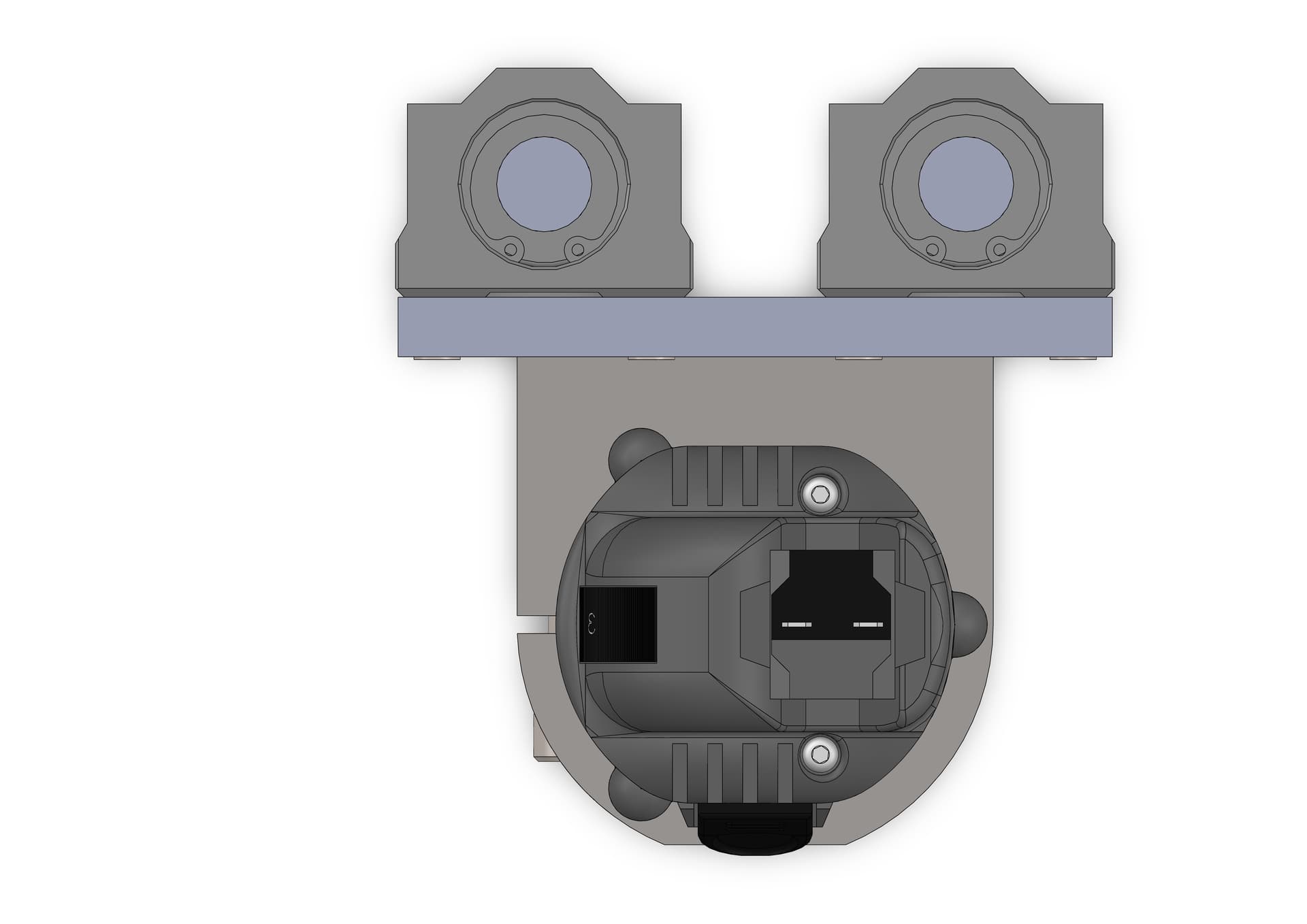
So I had a go at a clean build, from the center of linear rod’s to center of spindle would be 74mm, the house is 63mm long. It should be very easy to make, and the bearing blocks come in many different sizes and versions.
Now I just need to order my machine, I’ve landed on the Machinist version after going some back and forth with myself.
Enjoy
I forgot to give credit to the maker of the Kress spindle: Free CAD Designs, Files & 3D Models | The GrabCAD Community Library
Credit goes where credit belongs, thank you!


2 Likes
Early on in my rebuild I had similar thoughts but when I did the measurements I found that these bearing blocks did not have enough clearance (centre of rod to back plate of Z assembly). Also, finding an effective way of attaching the Z axis ball screw nut was problematic.
2 Likes
Okay, never easy I guess. I don’t have the full picture without the machine.
I didn’t either ![]() I just wanted to alert you before you went too far with purchases to support this particular solution.
I just wanted to alert you before you went too far with purchases to support this particular solution.
1 Like
I took a quick look, there seems to be room, but one may have to custom make a nut bracket. There are also more narrower linear rails housings and more shallow types. I don’t know how fare back one can go either. This is a 12mm ball screw from THK.


2 Likes
I couldn’t find any that fit - 18.5 mm from centre if 16 mm shaft to the back plate is all the room there is. If you have found one that can fit that (I would want it as long as possible to counter the leverage, and the best quality/tolerance you can find) then all should be good.
1 Like
Ok, I understand very tight, from center to back now is 19.5mm to backside of block and 23,2mm to arc on nut, but nut can be rotated 90 degree to gain some dept.
I just had some fun tonight, but maybe I can inspire someone, this is doable I think!
Have a good night


1 Like
Hey Marc,
what filament material did you use to print it?
Welcome to the forum!
Hey Terje,
yes it’s tight there (here you can see what the stock 65 mm mount looks like from the back when it’s disassembled) and since it seems that with this design of the Z assembly on the Onefinity, you would best try to keep the lever short, i.e. the center of the milling motor as close to the rails as possible, I find you considered that very well on your last design. When discussing spindles with higher weight and a bigger distance of the milling motor from the rails in order to clear the stepper, Tom @TMToronto and I indepently from each other came to the idea that the stability of the Z slider would be improved if one would mount two 80 mm mounts on top of the other. You would loose some Z travel though. A bit of loss of travel could be reduced by choosing shorter linear bearings. But I haven’t tried it out yet.
you’re not the only one who is enjoying what you have done here, I am too. Your designs show that for not having the machine yet, you are going very much in the right direction ![]() .
.
I have also had countless thoughts about this. The Z assembly on the Onefinity is the part I find most worth considering (besides the unappropriate connectors). However, I am not yet sure what I will finally choose. I also still have time as I have to move before I can get the machine up and running.
As for your latest design, I think it would be easier to ensure tighter clearances if it wasn’t bolted together from multiple pieces but milled as one piece from solid (basically). But I’m guessing you don’t have the ability to mill that yet (neither do I at the moment) and that you sound it out with the means one has.
But I’m leaning more towards not keeping the original Z rails assembly though.
And even if I absolutely demand and propagate the possibility to use motors with 43 mm Euro neck on the Onefinity, I don’t plan to use such carbon-brushed universal motors for milling, for me only an induction motor or a synchronous motor come into question.
But for drilling an array of holes into the base of the machine, I would appreciate it very much if I could clamp my drilling machine with reduction gear in it!
Thanks! It’s just garden variety petg but each layer has like 10 perimeters so it’s not only solid but has uhhhhh grain? Apparently a trick from the printed gun crowd.
1 Like